





|






|
|
| Service News | ||
|
|
Alfa MiTo
Version: All 1.4 TJet LPG Euro 4 models |
|
|||
| 1057 1 081 RA |
LPG SYSTEM WIRING
Power decrease/drop during acceleration - Service Solution |
|||
FAULT COMPLAINED OF
Power decrease and/or drop during acceleration while operating on LPG.
TECHNICAL CAUSE
Loss and/or intermittent continuity of some electrical connections close to the engine control unit connector.
OPERATIONS IN NETWORK
Network behaviour standards towards the Customer
- Once the customer's claimed fault is confirmed, reassure the customer that the fault will be solved by restoring the connection continuity for the LPG system wiring.
- After the operation, show the Customer what has been done and make sure he is satisfied.
Service Solution
Once the customer's claimed fault is confirmed, restore the continuity of the connections for the LPG system wiring, according to the Operating Cycle below.
OPERATION CYCLE
- Working in the engine compartment, disconnect the connector of the engine control unit (1 - Fig. 1).
Fig. 1
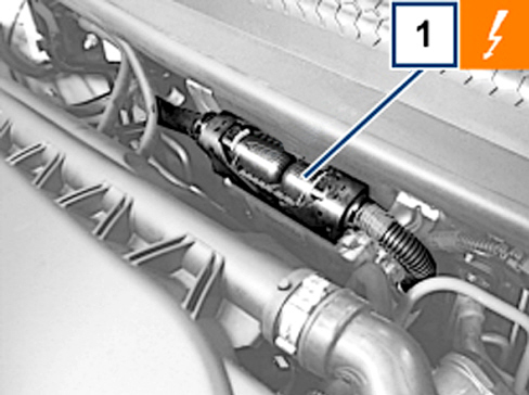

1 - M010B connector
- Working on the fasteners, remove the protection casing and the wiring fastening band.
- Remove the wiring protection tape until releasing the three following cables protected by insulating tape, as shown in Fig. 2:
- white-red cable connected to pin no. 25 (air temperature sensor signal);
- blue-red cable connected to pin no. 43 (water temperature sensor signal);
- red-green cable connected to pin no. 31 (ignition coil signal).
- Remove the insulating tape from the above cables and locate the welding (A – Fig. 2).
Fig. 2
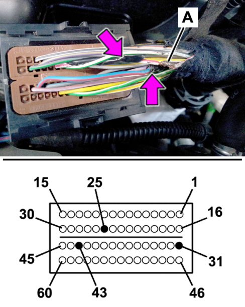
- Cut and remove the welding.
- Strip the cable ends by a max. length of 10 mm
- Join each cable in the proper way, proceeding as follows
Cable splicing
Splice the cables as shown, proceeding as described, with reference to Fig. 3.
- Apply on each cable section a thermal shrinking solder sleeve (A) suitable for the section, see Part&Service availability.
- Join the strands (D) of the cables as shown.
- Move the sleeve (A) until the splice is covered: the tin ring (C) should go next to the joined strands.
- Using a drier with heat shield tool 2000029200 (E) heat the sleeve (A).
- The sleeve (A) must be heated until the tin ring (C) melts, welding the splice, and the adhesive rings (B) stick to the cable.

|
Cautiously heat the sleeve (A) to prevent any damage. Wait until the sleeve cools down before handling the splice. |
Fig. 3
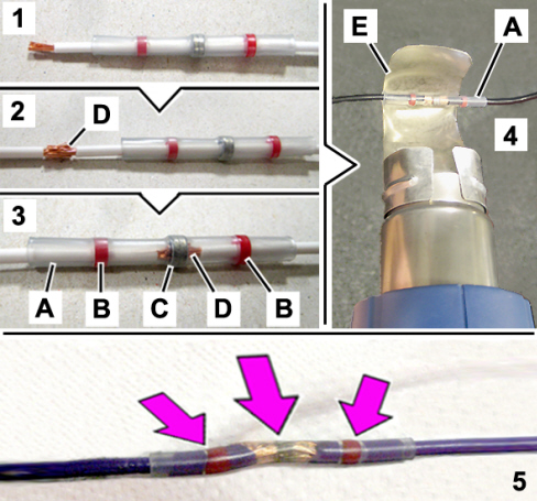
A. Thermal shrinking solder sleeve
B. Adhesive ring
C. Tin ring
D. Twisted strands
E. Heat shield - Tool no. 2000029200
- Restore the protection tape on the wiring
- Connect the connector to the injection control unit
AVALABILITY OF PARTS
|
Version |
Description |
Part No. |
Q.ty |
|
All models in question |
Thermal shrinking solder sleeve |
11105485 |
3 (*) |
(*) The pack contains no. 20 components
CLAIM REPORT DATA
|
Version |
Operation |
Part |
Fault |
Position |
Time allowance |
|
All models in question |
1057108 |
1 |
RA |
- |
0.40 |