





|






|
|
| Service News | ||
|
|
Alfa MiTo
Version: all models with lumbar adjustment |
|
|||
| 7045 1 401 MA |
FRONT SEATS
Noise - Service Solution |
|||

|
Cancels and replaces SN 70.05.12 of 23/03/2012 for Part Availability table upgrade |
FAULT COMPLAINED OF
Noise of the seat while leaning the back on it
TECHNICAL CAUSE
Noise / creaking caused by the rubbing between the components of the lumbar support.
OPERATIONS IN PRODUCTION
Installation of improved components.
IPLEMENTATION OF MODIFICATION
|
Version |
Factory |
Line |
Chassis No. |
Organisation No. |
|
All models in question |
Mirafiori |
- |
1180437 |
178637 |
OPERATIONS IN NETWORK
Network behaviour standards towards the Customer
- Once the customer's claimed fault is confirmed, reassure the Customer that the fault will be solved by replacing the noisy components with new, improved ones.
- After the operation, show the Customer what has been done and make sure he is satisfied.
Service Solution
Once the claimed fault is confirmed, replace the noisy components with new, improved ones according to the Operating Cycle below.
OPERATION CYCLE
After ascertaining that the noise comes from the lumbar area of the backrest, replace the noisy components, as described below, only on the seat featuring this fault, on the same car, without removing the seats and using the service kit no. 50525744.
- Move the seat fully forwards.
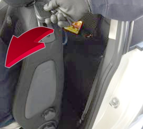
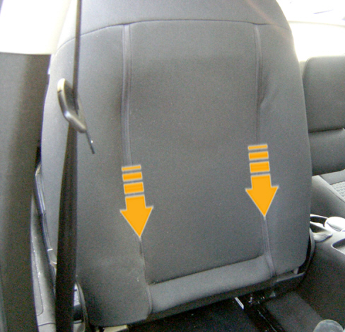
- Tilt the backrest fully forwards, as shown in Fig. 1.
Fig. 1

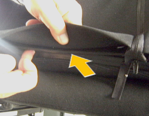
- Open the two hinges of the rear trim border of the backrest, as shown in Fig. 2.
Fig. 2
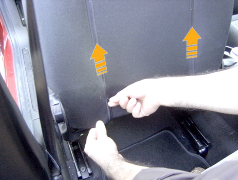
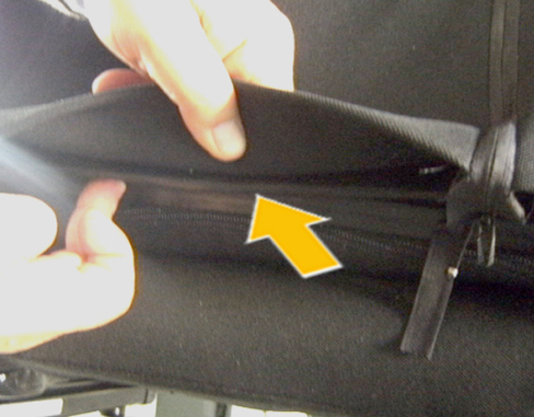
- Lift the lower border and release the fastening profiles, male and female, from the rear trim border, shown in the figure.
- Move the border under the head restraint to clear the work area.
Fig. 3
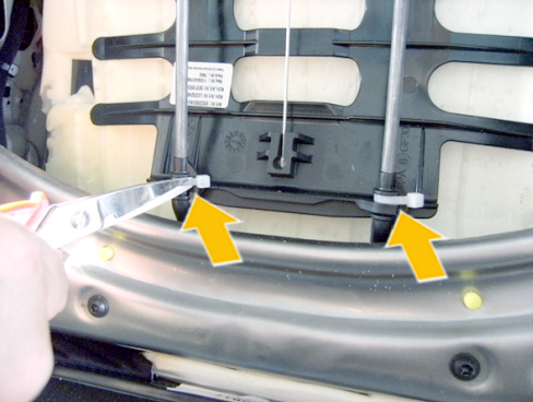
- Cut and remove the two strips, shown in the figure, under the lower securing area of the lumbar support.
Fig. 4
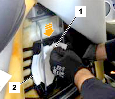
- Release the lumbar support control acting on the knob, on the external side of the seat and release the Bowden cable (1 - Fig. 5) from the housing on the rod, slightly pressing with your hand on the upper part.
- Remove and keep the sound insulation felt (2).
Fig. 5
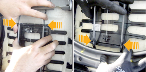
- Release the upper fasteners of the lumbar support, working in the points shown, then perform the same operation on the lower fasteners.
Fig. 6
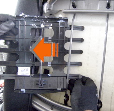
- Take out the plastic support from the side.
Fig. 7
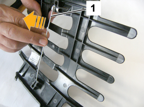
- Slightly press the ends of the support and take out the steel rod (1 - Fig. 8).
Fig. 8
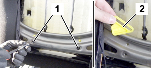
- Undo the two screws (1 - Fig. 9) fixing the lower plastic tracks in the internal area of the backrest crossmember.
- Remove the two tracks (2) from the sliding pins.
Fig. 9
Take the service kit no. 50525744 from the Spare Parts Dpt.
Fig. 10
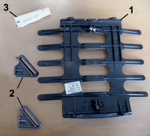
List of the components of the kit
1 - Lumbar support
2 - Lower tracks
3 - Specific Molykote G807 grease
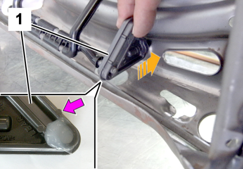
- Lubricate the new lower tracks (1 - Fig. 11) using specific Molykote G807 grease, in the lower area, until the first reference, as shown.
- Install the new lower tracks inside the backrest crossmember, checking the correct fitting of the alignment pins, as shown.
Fig. 11
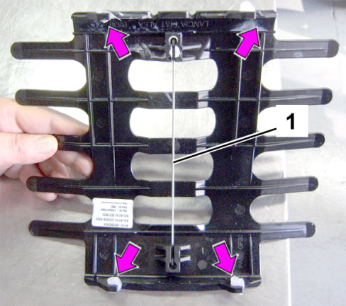
- Take the new plastic support from the kit, press the ends a bit and refit the steel rod (1 - Fig. 12) taken from the removed support.
- Apply specific grease, Molykote G807 type, from the kit, on the four fasteners.
Fig. 12
- Fit the plastic support between padding and sliding frame
- Secure the mounting engaging the fasteners for the bottom side.
Fig. 13
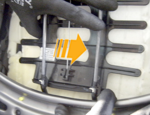
- Using a suitably-sized brush, apply specific Molykote G807 grease on the frame, in the points shown of the upper fastening area of the support.
- Secure the lumbar support at the top, engaging the fasteners.
Fig. 14
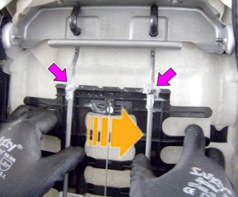
- Apply the previously removed noise insulating felt making it slide under the steel rod and arrange the borders on the frame as shown.
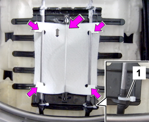
- Secure the lower fasteners with two bands (1 - Fig. 15) cutting the excess ends.
Fig. 15
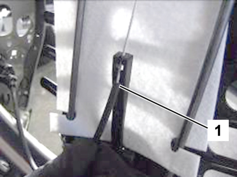
- Fit the adjustment Bowden cable (1 - Fig. 16) in the rod, paying attention to the correct position.
Fig. 16
- Reposition the border of the seat rear trim.
- Close the two hinges.
Fig. 17
- Lift the lower border and engage the fastening profiles, male and female, of the trim border, shown in the figure.
Fig. 18
Reposition the seat in the driving conditions.
AVALABILITY OF PARTS
|
Version |
Description |
Part No. |
Q.ty |
|
All models in question |
Service kit |
50525744 |
1 |
|
All models in question |
Band |
14560187 |
2 (*) |
(*) The pack contains 20 pieces
CLAIM REPORT DATA
|
Version |
Operation |
Part |
Fault |
Position |
Time allowance |
|
All models in question |
7045140 |
1 |
MA |
010 “ 090 |
0.30 |