





|






|
|
| Service News | ||
|
|
Alfa MiTo
Version: all models |
|
|||
| 4410 1 421 MA |
FRONT SHOCK ABSORBERS
Noise - Service Solution |
|||
FAULT COMPLAINED OF
Noise coming from front shock absorbers.
TECHNICAL CAUSE
Noisy support mounting for shock absorber on turret.
OPERATIONS IN PRODUCTION
Adoption of flexible mountings with improved thrust washers.
IPLEMENTATION OF MODIFICATION
|
Version |
Factory |
Line |
Chassis No. |
Organisation No. |
|
All models 1.4 MultiAir 105 HP |
Mirafiori |
- |
1169651 |
168535 |
|
All Models 1.4 Turbo MultiAir 135 HP |
Mirafiori |
1170014 |
168567 |
|
|
All models 1.3 MultiJet |
Mirafiori |
1170006 |
168568 |
OPERATIONS IN NETWORK
Network behaviour standards towards the Customer
- Once the claimed fault has been confirmed, reassure the Customer that the problem will be solved by replacing both flexible mountings with new ones, from the Spare Parts Dpt., having improved features.
- After the operation, show the Customer what has been done and make sure he is satisfied.
Service Solution
If the customer's claimed fault is confirmed, replace both flexible mountings with new ones, coming from the Spare Parts Dpt., according to the following Operating Cycle.
OPERATION CYCLE
Remove the front shock absorbers, with reference to Op. 4410A12 in the Service Manual, then proceed as follows.
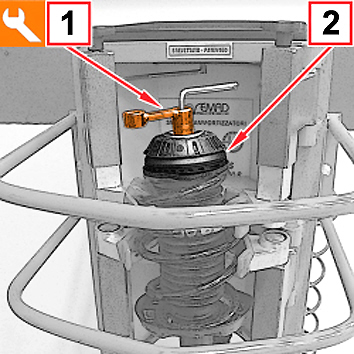
- Fit the shock absorber-spring assembly on the special tool no. 1874555001.
- Undo the fixing nut using the tool 1857509000 (1 - Fig. 1) and remove the flexible mounting (2).
Fig. 1

|
When refitting, always replace the fixing nuts with new ones from the Spare Part Dpt. |
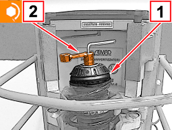
- Replace the removed flexible mounting with the new flexible mounting (1 - Fig. 2), from the Spare Parts Dpt.
- Install the new flexible mounting, tighten the new upper fixing nut and, using the special tool no. 1857509000 (2), tighten to the torque of 5.2 ÷ 5.7 daNm.
Fig. 2
Remove the shock absorber-spring assembly from the special tool and refit it on the vehicle.
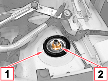
- Position the flexible plate (1 - Fig. 3).
- Screw in the nut (2) securing the shock absorber to the body without tightening it.
Fig. 3
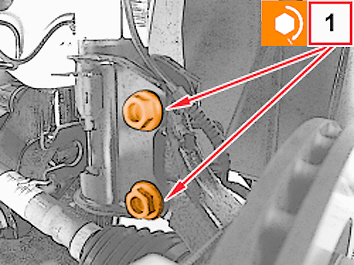
- Tighten the new bolts (1 - Fig. 4) securing the front wheel hub to the steering knuckle to a torque of 10.3 ÷ 12.6 + 45 .
Fig. 4
- Connect the articulation link (1 - Fig. 5) of the anti-roll bar , tighten the new fixing nut (2) to the torque of 3.6 ÷ 4.4 daNm.
Fig. 5
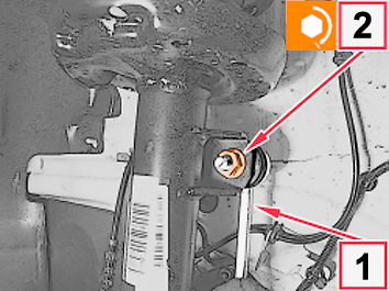
- Engage the brake oil pipe to the shock absorber bracket and close the retaining clip.
- Engage the wiring for the ABS wheel rpm sensor to the bracket for the shock absorber.
- Refit the (two) front wheels, with reference to Op. 4450B12 of the Service Manual.
- With the car on the ground, tighten the nut (1 - Fig. 6) securing the shock absorber to the body, screwed in previously, to the torque of 4.7 ÷ 5.2 Nm.

|
Before undoing the nut (1), insert the spanner correctly deep into the hexagonal groove at the top end of the shock absorber stem. |
Fig. 6
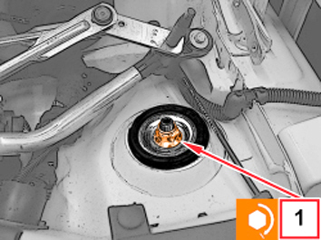
Repeat the operations carried out on the other side of the vehicle.
Check the front wheel geometry, with reference to Op. 4450A10 of the Service Manual.
AVALABILITY OF PARTS
|
Version |
Description |
Part No. |
Q.ty |
|
All models in question |
Flexible mounting |
50521707 |
2 |
|
All models in question |
Flexible mounting fixing nut |
55702313 |
2 (**) |
|
All models in question |
Self-locking nut (re. 2 - Fig. 5) |
12578321 |
2 (*) |
|
All models in question |
Screw (re. 1 - Fig. 4) |
51736811 |
4 (**) |
|
All models in question |
Self-locking nut (re. 1 - Fig. 4) |
51736810 |
4 (**) |
(*) The pack contains 5 components.
(**) The pack contains 20 components.
CLAIM REPORT DATA
|
Version |
Operation |
Part |
Fault |
Position |
Time allowance |
|
All models in question |
4410142 |
1 |
MA |
010-090 |
2.30 (*) |
(*) The Time Allowance includes the replacement of the flexible mountings plus front wheel geometry check.