





|






|
|
| Service News | ||
|
|
Alfa MiTo
All left-hand drive models with manual gearbox |
|
|||
| 3330 1 251 RG |
BRAKE PEDAL
Incorrect rotation/return movement with feeling of the vehicle braking and/or poor performance - Service Solution |
|||

|
Cancels and replaces the SN 33.01.11 of 13.04.2011 for Part Availability table upgrade. |
FAULT COMPLAINED OF
Incorrect rotation of the pedal, especially during return movement; in some cases there may be a residual torque at the brake calipers which, after long journeys, may cause the overheating of the pads and discs creating the feeling that the vehicle is braking and/or poor performance
TECHNICAL CAUSE
Matching tolerances between pedal, bush and pin.
OPERATIONS IN PRODUCTION
New, improved pedal unit.
IPLEMENTATION OF MODIFICATION
|
Version |
Factory |
Line |
Chassis No. |
Organisation No. |
|
All models in question |
Mirafiori |
- |
1028276 |
29369 |
OPERATIONS IN NETWORK
Network behaviour standards towards the Customer
-Once the claimed fault is confirmed, reassure the Customer that the fault will be solved by restoring the pedal unit proper operation.-After the operation, show the Customer what has been done and make sure he is satisfied.Service Solution
Once the customer's claimed fault is confirmed (having ascertained that the handbrake linkage is correctly released), check that the pedal unit is working properly and, if necessary, replace the non-compliant components, according to the Operating Cycle below.
OPERATION CYCLE
 | The procedure described below should be performed with the handbrake released. |
Once the claimed fault is confirmed, proceed as described below:
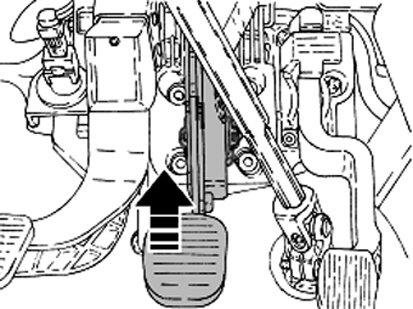
Position the vehicle safely then, with engine running, pull the brake pedal upwards gripping it by the footrest as shown in Fig. 1 and check that the vehicle is released.
Fig. 1
If the vehicle is released, the brake pedal (1), the bushes (2), the fulcrum pin (3) and the clip (4) shown in fig. 2 must be replaced by the new parts from the Spare Parts Dpt., with reference to Op. 3330B22 of the Service Manual.
Fig. 2
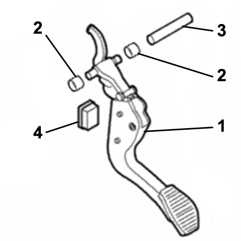
1 - Complete brake pedal
2 - Bush
3 - Pin
4 - Clip
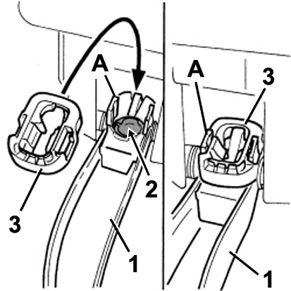
| During removal, keep the cap (2 - Fig. 3) for brake servo push rod laying. |
Using the new parts from the Spare Parts Dpt.:
-install the bushes (2 - Fig. 2) on the brake pedal;-place the cap (2 - Fig. 3) for the servo brake push rod head laying on the brake pedal (1), as shown;-install the new clip (3) on the brake pedal (1) making sure that the fixing clips (A) are securely fastened, as shown;Fig. 3
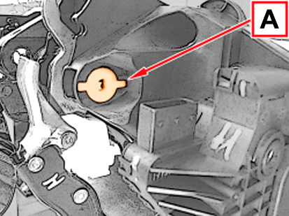
| Check that the head of pin (A - Fig. 4) is locked with the splining for the pedal unit mounting, as shown. |
Fig. 4
AVALABILITY OF PARTS
|
Version |
Description |
Part No. |
Q.ty |
|
All models in question |
Complete brake pedal |
77366184 |
1 |
|
All models in question |
Pin |
71747803 |
1 |
|
All models in question |
Bush |
71740397 |
2 |
|
All models in question |
Clip |
71747693 |
1 |
CLAIM REPORT DATA
|
Version |
Operation |
Part |
Fault |
Position |
Time allowance |
|
All models in question |
3330125 |
1 |
RG |
- |
0.60 |