




|






|
|
| Service News | ||
|
|
Alfa MiTo
all versions |
|
|||
| 5550 D 000 AA |
BRAKE LIGHTS
Brake pedal switch operation fault diagnosis - Service Manual Update |
|||
|
In addition to the information in the Service Manual, we are enclosing the fault diagnosis for the operation of the brake pedal switch.
FAULT COMPLAINED OF
The brake lights are not working properly.
OPERATIONS IN NETWORK
Following the fault diagnosis on the operation of the brake lights:
I 014 - Brake lights and third brake light not working;
I 015 - (Side) brake lights not working;
I 016 - Middle (third) brake light not working;
before replacing the switch, carry out the diagnostic procedure on the operation described below.

|
The side brake lights are activated by the Body Computer Node whilst the third brake light is controlled directly by the switch on the brake pedal. |
Brake pedal switch not working properly
|
Step |
Operations to be carried out |
All OK |
Problems encountered |
Operation |
|
0 |
Press the brake pedal several times and check that the brake lights are activated correctly each time |
End of diagnosis The fault should not be sought in the switch |
The fault persists. |
Before replacing the switch, move on to step 1 to carry out the fault diagnosis on its operation. |
|
Step |
Cursor efficiency check |
All OK |
Problems encountered |
Operation |
|
1 |
Remove the switch, with reference to Op. 5550D10, in the Service Manual without disconnecting the electrical connection. Press the switch cursor manually several times checking that the travel takes place in both directions fully and without impediments. Check that the brake lights are activated correctly each time |
End of Fault Diagnosis The fault should not be sought in the switch |
The lights are not activated correctly. |
Move on to step 2. |
|
The cursor slides with difficulty and does not reach the end of travel correctly. |
Replace the switch. |
|||
|
Step |
Signal check |
All OK |
Problems encountered |
Operation |
|
2 |
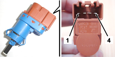
Disconnect the electrical connection from the switch. Check that the signal is correct by connecting a multimeter to pins 2 and 3 of the switch (see Fig. 1): Press the cursor manually (brake pedal released condition) and check that the continuity is interrupted. Release the cursor (brake pedal pressed condition) and check that there is continuity. |
Move on to step 3. |
Signal interrupted or not correct. |
Replace the switch |
|
Step |
Signal check |
All OK |
Problems encountered |
Operation |
|
3 |
Check that the signal is correct by connecting a multimeter to pins 1 and 4 of the switch (see Fig. 1): Press the cursor manually (brake pedal released condition) and check that there is continuity. Release the cursor (brake pedal pressed condition) and check that the continuity is interrupted. |
End of diagnosis The fault should not be sought in the switch |
Signal interrupted or not correct. |
Replace the switch |
Fig. 1