





|





|
|
| Service News | ||
|
|
Alfa MiTo
all versions with vehicle dynamic control (DNA) |
|
|||
| 7040 L 000 AA |
VEHICLE DYNAMIC CONTROL SELECTOR (DNA)
Operation fault diagnosis - Service Manual Update |
|||
|
In addition to the information in the Service Manual, we are enclosing the fault diagnosis for the operation of the Vehicle Dynamic Control Selector (DNA).
FAULT COMPLAINED OF
-DNA selector not working properly;-The LEDs on the DNA selector do not come on properly.OPERATIONS IN NETWORK
Carry out the fault diagnosis on the Vehicle Dynamic Control Selector (DNA) operation:
Vehicle dynamic control selector (DNA) not working properly
|
STEP |
OPERATION TO BE CARRIED OUT |
ALL OK |
PROBLEMS ENCOUNTERED |
ACTION |
|
1 |
CHECK USING DIAGNOSTIC EQUIPMENT Connect the diagnostic equipment to the car and check for the presence of errors in the following control units: electric steering control unit; ABS/ESP control unit; engine management control unit; |
Move on to Step. 2 |
Presence of errors at: electric steering control unit; ABS/ESP control unit; engine management control unit. |
Continue following the instructions given by the diagnostic equipment. |
|
2 |
DNA SELECTOR OPERATION CHECK Check that the DNA selector is working properly by carrying out Test 7040LA, described below. |
Move on to Step. 3 |
Vehicle dynamic control selector not working properly. |
Replace the dynamic control selector with reference to Op. 7040L53 in the Service Manual. |
|
3 |
CHECK ON EFFICIENCY OF SIGNALLING LED Check that the signalling LEDs come on correctly depending on the mode set (see Fig. 1). Using an ohmmeter connected to the various terminals (see - Fig. 2) check that the resistance values correspond to those in Table A |
Move on to Step 4 |
One or more of the signalling LEDs not working properly. |
Replace the dynamic control selector with reference to Op. 7040L53 in the Service Manual. |
|
4 |
CONTINUITY CHECK Check the continuity of the wiring between the Body Computer and the dynamic control selector. |
End of diagnosis |
Circuit broken. |
Restore the correct wiring. |
Test 7040LA - Check on correct operation of Vehicle Dynamic Control Selector (D.N.A.)
|
STEP |
CHECK TO BE PERFORMED |
REMEDIAL ACTION IF THE CHECK IS NOT OK |
|
1 |
Dynamic Mode Control Disconnect the wiring side connector for the dynamic control selector; Place the dynamic control selector in Dynamic Mode (ref. d - Fig. 1); Select the ohmmeter function on the Examiner equipment; Connect the probes between pins 4 and 5 (ref. Fig. 2) of the dynamic selector connector and check that the resistance value is in the following range. - Min. 215.6 Ohms - Max 224.4 Ohms |
Replace the vehicle dynamic control selector; [PR_7040L53] |
|
2 |
Normal Mode Control Disconnect the wiring side connector for the dynamic control selector; Place the dynamic control selector in Normal Mode (ref. n - Fig. 1); Select the ohmmeter function on the Examiner equipment; Connect the probes between pins 4 and 5 (ref. Fig. 2) of the dynamic selector connector and check that the resistance value is in the following range. - Min. 1950.2 Ohms - Max 2029.8 Ohms |
Replace the vehicle dynamic control selector; [PR_7040L53] |
|
3 |
All Weather Mode control Disconnect the wiring side connector for the dynamic control selector; Place the dynamic control selector in the All Weather Mode position (ref a - Fig. 1); Select the ohmmeter function on the Examiner; Connect the probes between pins 4 and 5 (ref. A - Fig. 2) of the dynamic selector connector and check that the resistance is within the following range: -Min. 646.2 Ohms - Max 703.8 Ohms |
Replace the vehicle dynamic control selector; [PR_7040L53] |
Fig. 1
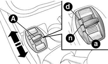
A = Mode selection lever
a = All Weather mode (mode for driving in poor grip conditions);
n = Normal mode (mode for normal driving conditions);
d = Dynamic mode (mode for sports driving).
Vehicle Dynamic Control Selector connector pin out (DNA)
Fig. 2
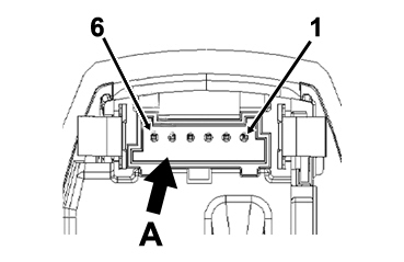
Table A
|
Function |
Terminal |
Resistance / Ohms | |
|
Min |
Max | ||
|
Dynamic Mode |
4 - 5 |
215.6 |
224.4 |
|
All Weather Mode |
4 - 5 |
646.2 |
703.8 |
|
Normal Mode |
4 - 5 |
1950.2 |
2029.8 |
|
LED |
- |
- |
- |
|
Dynamic mode lighting (Amber) |
1 - 2 |
Infinite |
Infinite |
|
All Weather mode lighting (Blue) |
1 - 3 |
Infinite. |
Infinite. |
|
Normal mode lighting (White) |
1 - 5 |
Infinite. |
Infinite. |
|
Symbol lighting (Red) |
1 - 5 |
Infinite |
Infinite |