




|






|
|
| Service News | ||
|
|
Alfa MiTo
all versions |
|
|||
| 0000 0 000 AA |
NEW MiTo MODEL
Main technical specifications |
|||
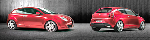
The new Alfa Marque model (Fig. 1) is being launched with the name "MiTo".
Fig. 1 - Alfa Romeo MiTo, ¾ front and rear view
The new model comes in a very compact 3 door version and will initially be available with three different engine types:
-aspirated petrol (1.4 - 78 bhp)-turbocharged petrol (1.4 - 155 bhp)-turbodiesel (1.6JTDM - 120 bhp)all engine types will be fitted with six speed gearboxes.
All the engines are produced in a EURO 5 READY version, in other words that complies with the E5 directive limits that will come into force in the near future.
The new model is available in three types of trim level: Progression, Distinctive and Sport.
The planned maintenance interval is 30,000 km for petrol versions and 35,000 km for diesel versions.
The excellent engine performance is complemented by tried and tested mechanics with improvements in comfort and handling achieved through technical innovations such as, for example, the ALFA dna system.
The new MiTo also provides a high specification level in terms of entertainment as a result of collaboration with the best partners in each sector as exemplified by the Bose Hi-fi radio with CD player and MP3 with controls on the steering wheel and the "Blue&Me"® system produced with Microsoft.
The pages which follow contain the identification data, dimensions and main technical specifications for the different engine types and a brief description of the main innovative/important features of the new model.
Identification data
Engine codes and bodywork versions
|
VERSION |
ENGINE |
BODYWORK |
GEARBOX |
|
1.4 Petrol (4 seater) (*) |
955A1000 |
955AXB1B 01 |
6 speed |
|
1.4 Petrol (5 seater) (*) |
955A1000 |
955AXB1B 01B |
6 speed |
|
1.4 Turbo Petrol (4 seater) |
199A8000 |
955AXA1B 00 |
6 speed |
|
1.4 Turbo Petrol (5 seater) |
199A8000 |
955AXA1B 00B |
6 speed |
|
1.6 JTDM (4 seater) |
955A3000 |
955AXC1B02 |
6 speed |
|
1.6 JTDM (5 seater) (*) |
955A3000 |
955AXC1B02B |
6 speed |
(*) versions for specific markets
Dimensions
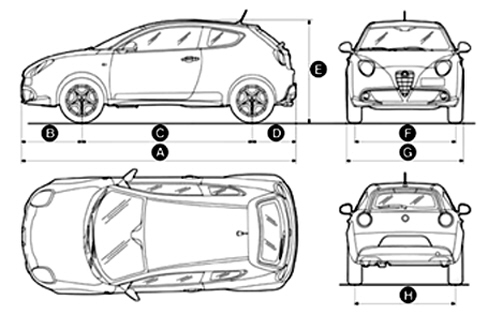
Fig. 2 - Vehicle dimensions in mm (with vehicle unladen and standard tyres)
|
A |
B |
C |
D |
E |
F |
G |
H (*) |
|
4063 |
904 |
2511 |
648 |
1453 |
1477 (+) 1483 (++) |
1720 |
1469 (+) 1475 (++) |
Small variations in size are possible depending on the dimensions of the rims
(+) with 215/40R18 tyres
(++) with 195/55R16 tyres
Engines
The new MiTo will initially be available with three different engines (1.4 Petrol - 78 bhp, 1.4 Turbo Petrol - 155 bhp and 1.6 JTDM - 120 bhp already in use on other Group models) transversely mounted at the front with the specifications described below:
|
1.4 Petrol | |
|
Engine marking |
955A1000 |
|
Total capacity |
1368 cc |
|
Max power CEE |
58kW (78 bhp) |
|
At a speed of |
5750 rpm |
|
Max torque CEE |
120 Nm (12.2 kgm) |
|
At a speed of |
4000 rpm |
|
Timing |
TOHC |
|
Fuel system |
Multipoint electronic injection |
|
Top speed |
km/h 165 |
|
1.4 Turbo Petrol | |
|
Engine marking |
199A8000 |
|
Total capacity |
1368 cc |
|
Max power CEE |
114kW (155 bhp) |
|
At a speed of |
5500 rpm |
|
Max torque CEE |
201Nm (20,5 kgm) - 230Nm (23,5 kgm) (*) |
|
At a speed of |
5000 rpm - 3000 rpm (*) |
|
Timing |
TOHC |
|
Fuel system |
Multipoint electronic injection with turbo and intercooler |
|
Top speed |
km/h 215 |
(*) In Dynamic mode
|
1.6JTDM | |
|
Engine marking |
955A3000 |
|
Total capacity |
1598 cc |
|
Max power CEE |
88kW (120 bhp) |
|
At a speed of |
3750 rpm |
|
Max torque CEE |
280Nm (28.5Kgm) - 320Nm (32.6 kgm) (*) |
|
At a speed of |
1500 rpm -1750 rpm (*) |
|
Timing |
TOHC |
|
Fuel system |
Common Rail Multijet direct injection with turbo and intercooler |
|
Top speed |
km/h 198 |
(*) In Dynamic mode
Description of the 1.4 petrol engine
The Alfa MiTo is aimed at young customers with a "new" petrol engine, illustrated in Fig. 3, with the following special features: low consumption, simple construction, strong and reliable.
Fig. 3
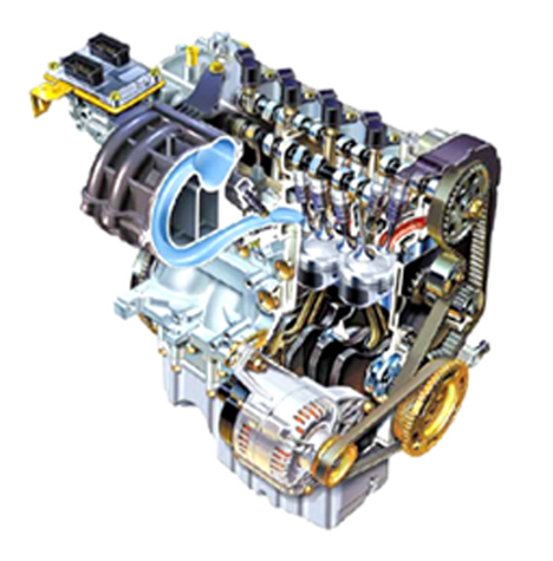
The 4 cylinder in line engine with a twin overhead camshaft, 16 valves regulated by a continuous timing variator and Bosch ME 7.6.3. integrated electronic injection-ignition provides a maximum power output of 78 bhp at 5750 rpm. The timing control is produced through a toothed belt and hydraulic tappets.
The exhaust gas recirculation (E.G.R.) in the combustion chamber is achieved by delaying the opening of the exhaust valves.
However, the presence of the exhaust gases (up to 25%) does not adversely affect rapid and regular combustion because a system of shuttering the inlet ducts and the special asymmetrical design of the ducts themselves considerably increases the level of turbulence.
The variation in turbulence, between low speeds and full load conditions, is achieved through a slider valve composed of a suitably shaped plate that slides between the intake manifold and the cylinder head plane opening or closing one of the two inlet ducts for each cylinder.
The use of improved performance exhaust and intake manifolds contributes to the reduction in consumption and pollutant emissions.
Description of the 1.4 turbo petrol engine
The Alfa MiTo has a "new" supercharged petrol engine known as the Turbo Petrol, illustrated in Fig. 4. Its special features are: performance, responsive acceleration, low consumption, simple construction, robustness and reliability.
Fig. 4
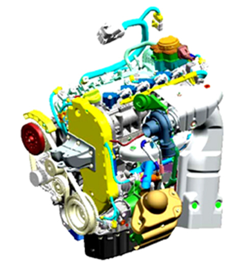
The new 1.4 Turbo Petrol engine has a maximum power output of 155 bhp at 5500 rpm and a maximum torque of 201 Nm at 5000 rpm (230 Nm at 3000 rpm in Dynamic mode where available). This allows considerable driving flexibility, with reduced use of the gears, whether you want a pleasant, relaxed driving style or gritty responsiveness when the driver asks the engine to provide power in the kick-down stage.
The reduced inertia of the turbocharger allows maximum performance without the normally tiresome associated delays.
Special attention has been paid to the design of the fluidynamics and to combustion to minimize energy losses and produce excellent performance whilst keeping consumption down.
The fixed geometry Garrett turbocharger managed by the Engine Management Node by means of a solenoid that regulates the waste gate actuator and a shut off valve is reponsible for supercharging.
The intake circuit is illustrated in Fig. 5
Fig. 5
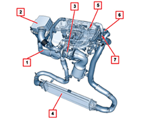
Key
1. Dynamic air intake
2. Air filter
3. Turbocharger
4. Intercooler
5. Intake manifold
6. Motorized throttle body
7. Shut-off solenoid
Circuit description
The intake air goes from the dynamic air intake (1 - Fig. 5), located in the area of the front crossmember, via a pipe, to the air filter (2).
After having undergone the filtering process, the air is sent to the turbocharger (3) via a main pipe where the pipes coming from the following systems converge:
-Shut-off solenoid valve system-Crankcase oil vapour recirculation system-Fuel evaporation control systemThe compressed and heated air goes from the turbocharger to the intercooler (4) where it is cooled by the outside air acting on the elements of the heat exchanger then the compressed air reaches the motorized throttle body, via a pipe, and from there is directed to the intake manifold (5).
A turbo pressure sensor and the connection to the shut-off valve (7) are located on the connecting pipe between the intercooler and the throttle body.
The following are fitted on the intake manifold:
-The motorized throttle body (6)-The intake air pressure/temperature sensor-The fuel manifold with injectors and differential pressure regulator-The fuel evaporation control system valve assembly.The differential pressure regulator for the fuel supply system is connected to the intake manifold via a rubber pipe.
Turbocharger description
The Garrett turbocharger, illustrated in Fig. 6, is the IHI RFH3 type with a waste gate valve managed by the injection control unit by means of a turbo pressure solenoid.
Supercharging allows improved performance at low engine speeds, in order to make driving the vehicle more pleasant, without an excessive increase in fuel consumption.
Fig. 6
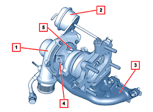
Key
1. Turbocharger
2. Waste gate valve actuator
3. Exhaust manifold
4. Coolant inlet
5. Lubrication oil inlet
The turbocharger (1 - Fig. 6) is connected directly to the oil filter (green filter) for the lubrication of the impeller and the cooling of the actual turbocharger.
The turbocharger is connected to the engine cooling circuit through dedicated pipes with natural type circulation.
The connection with the engine cooling circuit (4) has the task of preventing a sudden change in temperature which takes place when the engine is switched off.
Solenoid valve
The solenoid valve (1 - Fig. 7) comprises a plastic casing that encloses a shutter and an electromagnet.
It is connected, via flexible pipes, to:
-turbocharger outlet (high pressure intake)-waste gate valve actuator (3)-turbocharger air intake pipe (excess air pressure discharge).Fig. 7
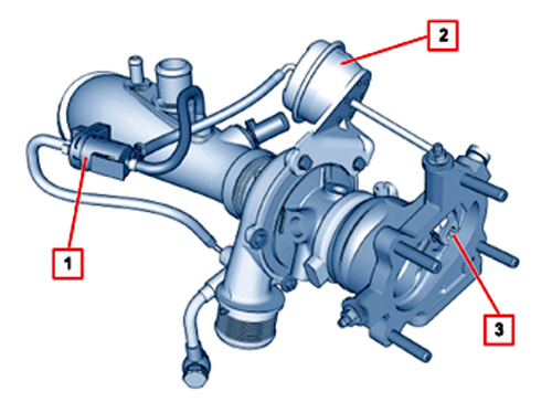
Key
1. Solenoid valve
2. Waste gate valve actuator
3. Waste gate valve
The injection control unit measures the supercharging pressure in all engine operating ranges through the turbo pressure sensor. If this pressure exceeds the pre-set values, the control unit intervenes on the solenoid valve supplying the electromagnet which, attracting a shutter, releases the high pressure flow to the actuator thereby allowing the opening of the waste gate valve.
Once the regulation action is over, the electromagnet is no longer supplied and the high pressure is discharged upstream of the turbocharger.
Description of the 1.6 jtdm engine
The new MiTo has a new, supercharged 1.6 JTDM diesel engine, illustrated in Fig. 8, from the JTDM (Multijet) family providing a maximum power output of 120 bhp at 3750 rpm and a maximum torque of 280 Nm at 1500 rpm (320 Nm at 1750 rpm in Dynamic mode where available). This engine features performance, responsive acceleration, low consumption, simple construction, robustness and reliability.
The new engine has a vacuum operated variable geometry turbocharger controlled by the engine management node with a position sensor.
The planned maintenance interval is 35,000 km, without the need for a service in between.
Fig. 8
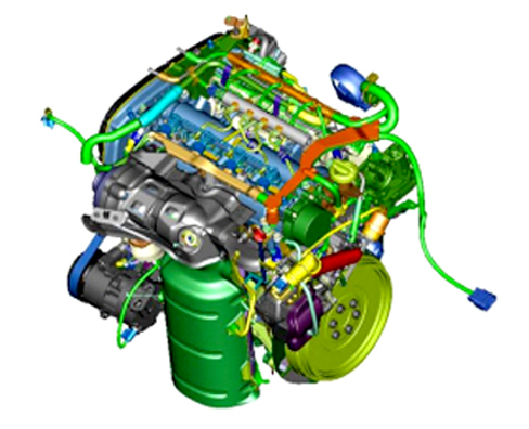
The table below contains a brief description of the main components of the new JTDM (Multijet) engines:
|
Component |
Description |
|
Cylinder head |
Made in two parts: camshaft housing and head in aluminium alloy |
|
Cylinder block/crankcase |
Made from cast iron |
|
Crankshaft |
Steel with 8 counter-weights and 5 supports |
|
Timing |
Two overhead camshafts. Toothed belt controlling the single exhaust camshaft and idler at the intake shaft through geared torque with clearance recovery. Hydraulic tappets and 4 valves per cylinder. |
|
Engine management |
BOSCH EDC 16 C39 engine management system |
|
Air supply |
With variable geometry turbocharger and air/air heat exchanger (intercooler). |
|
Lubrication |
Forced with geared pump, green filter filtration system and oil/engine coolant heat exchanger. |
|
Cooling |
Forced fluid circulation through centrifugal pump and sealed circuit; radiator and additional expansion tank. |
Systems
Below is a brief description of the main diagrams and systems:
A) Air intake circuit
B) Timing belt diagram
C) Turbocharger
D) EGR system
E) Engine oil lubrication circuit
A) air intake circuit
It should be remembered that the air, as in other JTDM systems, passes through the flow meter straight after the filtering process and reaches the turbocharger.
From the turbocharger the compressed and heated air moves on to the intercooler, where it undergoes a heat exchanger with the outside and cools down, then the compressed air reaches the motorized throttle body, via a rigid pipe, and then it reaches the intake manifold.
The connecting pipe between the intercooler and the intake manifold has special couplings to produce a damping effect during supercharging.
The following are fitted on the intake manifold:
-The motorized throttle body-The intake air pressure/temperature sensor-The pipes coming from the crankcase gas recirculation system.Fig. 9 - Air intake circuit
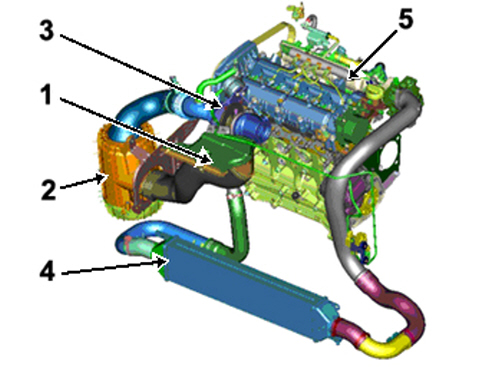
Key
1. Air intake
2. Air filter
3. Turbocharger
4. Intercooler
5. Intake manifold
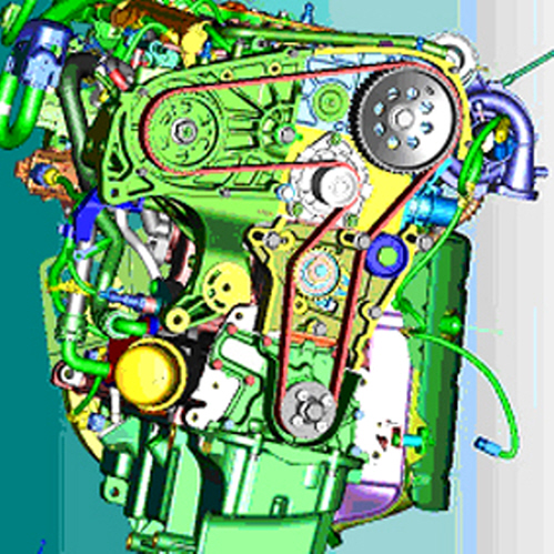
B) timing belt diagram
The components are similar to those for the 1.9 JTDM 16v; whilst the belt is specific, see Fig. 10.
Fig. 10 - Timing belt
C) turbocharger (variable geometry)
Variable geometry turbocharger (VGT) (Fig. 11) managed by the Engine Management Node through the vacuum solenoid and turbine vane direction actuator position sensor.
Fig. 11
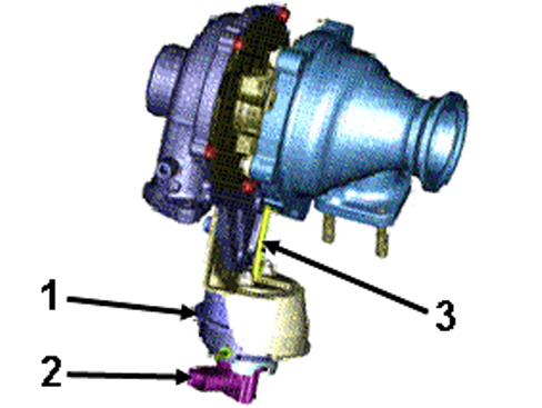
Key
1. Pneumatic actuator
2. Position sensor
3. Turbine vane direction rod
Operation
The (air temperature and pressure) sensor fitted on the intake manifold read the supercharging pressure for the air flow rate passing through the manifold.
Then the (air temperature and pressure) sensor sends this information directly to the engine management node, parallel to this measurement a direct control of the pneumatic actuator position is added via the position sensor that directs the turbine vanes as appropriate.
Fig. 12 - Variable Geometry Turbo (VGT) control system diagram
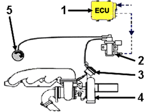
Key
1. Engine management node
2. Vacuum regulation solenoid
3. Vacuum pneumatic actuator with position sensor
4. Variable geometry turbo
5. Vacuum reservoir
D) egr system
The EGR system (Fig. 13) and EGR valve (Fig. 14) components are illustrated below.
Fig. 13 - EGR system components
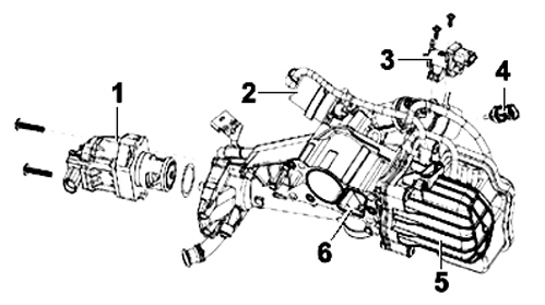
Key
1. EGR valve
2. EGR by-pass actuator
3. By-pass actuator control solenoid
4. Coolant temperature sensor
5. EGR exchanger
6. EGR by-pass
Fig. 14 - EGR valve components
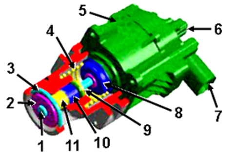
Key
1. Stem
2. Valve
3. Valve bore
4. Spring
5. DC motor
6. Valve position sensor
7. Electrical connector
8. Spring reaction cup
9. Sealing system
10. Sliding guide
11. Filter seal
Description
The recirculation of the exhaust gases (EGR - Exhaust Gas Recirculation) is used on engines to reduce the emission of nitrogen oxides (NOX).
The mass of gases recirculated is basically composed of residual air that has not been involved in the eariler combustion process and the products of combustion (carbon dioxide and water vapours in particular). The latter two chemical compounds have a greater thermal capacity than the air they replace and therefore the average thermal capacity of the total charge, fresh intake air and recirculated exhaust gases will be higher.
Thanks to this increased thermal capacity of the total charge, there is a descrease in the temperature of the flame with a consequent reduction in the oxidation speed of the fuel; all of this produces a slowing down in the process of the formation of nitrogen oxides (NOX).
EGR technology has also undergone considerable development with the development of regulations governing harmful emissions: it has moved on from a simple on-off valve to a gas modulating valve and then a heat exchanger has been introduced to lower the temperature of the recirculated gases.
The use of a heat exchanger has become necessary because the as the recirculated gases find themselves at a greater temperature than the intake air, the temperature of the charge entering the combustion chamber increases, decreasing volumetric efficiency. As the burnt gases are directed into a heat exchanger their temperature descreases thereby allowing a greater mass and a lower temperature for the intake charge with obvious benefits in terms of restricting nitrogen oxide NOX emissions.
The new EGR module, in addition to having a new type of modulating valve, makes it possible to decide whether or not to cool the recirculated gases by means of a by-pass.
This function, managed completely by the engine management node, makes it possible to improve the operation of the EGR in terms of reducing nitrogen oxides without penalizing the emission of hydrocarbons (HC) and carbon monoxide (CO).
Fig. 15
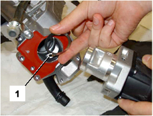
 | Each time the EGR valve is detached, the metal seal (1 - Fig. 15) must be replaced to prevent any exhaust gas seepage not controlled by the system. |
Advantages
The advantages offered by the new EGR valve are:
-Presence of a plate position sensor which allows improved operational control and diagnosis.-Increased activation force, therefore less sensitive to getting stuck.-Single plate with less sensitivity to seepage problems as a resultE) engine oil lubrication circuit
The engine oil lubrication circuit diagram is illustrated below
Fig. 16 - Engine oil lubrication circuit diagram (approximate diagram)
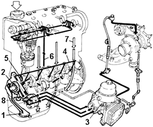
Key
1. Suction head with filter mesh
2. Oil pump
3. Engine oil filter integrated system
4. Main longitudinal duct
5. Jets (piston skirt cooling)
6. Vertical channel (camshaft mountings lubrication)
7. Oil falling back into sump
8. Switch for engine oil pressure warning light
Alfa dna system
(for certain versions/markets)
The Alfa Romeo MiTo is the first Alfa to use the ALFA dna system (Fig. 17).
The dna is an innovative device which, working on the vehicle dynamic control systems, adjusts the car setup to meet the customer''s requirements, intervening on the on board electronics responsible for the management of most of the mechanics.
The ALFA dna system has three operating modes (d, n, a) which the customer selects between using the lever (A - Fig. 17):
d - dynamic: sports driving mode.
n - normal: driving mode for normal conditions.
a - all weather: driving mode for poor grip conditions (rain, snow).
Fig. 17
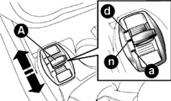
and acts on the components for controlling the vehicle dynamics, such as:
-Engine Management Control Unit-Instrument Panel-VDC system-SteeringLever
Lever A - (Fig. 17) is the mono stable type and therefore always remains in a central position.
The driving mode selected is signalled by the corresponding LED coming on and the reading in the left corner of the reconfigurable multifunction display (Fig. 18) as illustrated below:
Fig. 18
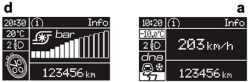
d - Dynamic mode
a - All Weather mode
| We should remember that when the Normal mode is selected there will be no writing or symbol in the display. |
Switching the Dynamic mode on/off
To turn the Dynamic mode (Fig. 19) on, move the lever upwards (to d) (Fig. 17) and stay in this position for 0.5 seconds until the LED lights up or the word Dynamic appears in the instrument panel display as illustrated:
Fig. 19
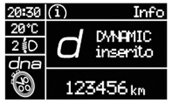
Later on, when lever A (Fig. 17) is released it returns the its central position.
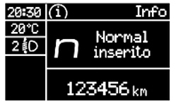
To turn the Dynamic mode off, and return to Normal, repeat the same movement with the lever with the same time scales but, in this case, the LED that will light up will be the one for the Normal position and the panel will show the reading Normal as illustrated in Fig. 20.
Fig. 20
Switching the All Weather mode on/off
To turn the All Weather mode on, move the lever downwards (letter a) and remain in this position for 0.5 seconds or until the LED lights up or the panel shows the words All Weather as illustrated in Fig. 21.
Fig. 21
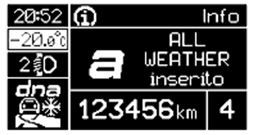
To turn the All Weather mode off and return to Normal, the procedure is the same as described for the Dynamic mode with the difference being that in this case the lever should be moved downwards to the letter a.
It is not possible to go directly from Dynamic mode to All Weather mode and viceversa. It is always necessary to return to Normal mode and then select the other configuration.
If Dynamic mode was on before the engine was switched off, the configuration will automatically be Normal mode when it is restarted.
If, on the other hand, All Weather or Normal mode was on before switching off, the configuration will be maintained when the engine is next started.
The Dynamic mode cannot be turned on when the vehicle speed exceeds 110 Km/h.
If there is a system or lever (A - Fig. 17) failure, no configuration can be engaged and there will be a warning message in the panel display.
Gearboxes
The following type of gearbox is fitted on the 1.4 Petrol version:
-C514 with 6 forward speeds with synchromesh plus reverse;|
1st |
2nd |
3rd |
4th |
5th |
6th |
Reverse |
|
1:3,909 |
1:2,158 |
1:1,480 |
1:1,121 |
1:0,921 |
1:0,766 |
1:3,909 |
The following type of gearbox is fitted on the 1.4 Turbo Petrol and 1.6 JTDM versions:
-M32 with 6 forward speeds with synchromesh plus reverse;|
1st |
2nd |
3rd |
4th |
5th |
6th |
Reverse |
|
1:3,818 |
1:2,158 |
1:1,475 |
1:1,067 |
1:0,875 |
1:0,744 |
1:3,545 |
Braking system
The Alfa MiTo is available (certain versions/markets) with the most sophisticated auxiliary electronic or mechanical systems, namely:
VDC system (Vehicle Dynamic Control)
In addition to the ABS there is a VDC vehicle stability control system which helps in maintaining directional control if the tyres lose grip; the VDC, in turn, includes the following systems:
-Hill Holder-ASR-Brake Assist-MSR-CBC-ELECTRONIC Q2 (E-Q2)-DSTHill Holder system
The Hill Holder system facilitates setting off on a hill and is automatically activated in the following cases:
-uphill: vehicle stationary on a road with a gradient of more than 5%, engine on, clutch and brake pedals pressed and gearbox in neutral or gear (other than reverse) engaged;-downhill: vehicle stationary on a road with a gradient of more than 5%, engine on, clutch and brake pedals pressed and reverse gear engaged.During take off the VDC system control unit maintains the braking pressure at the wheels until the engine torque required for departure is reached or for a maximum of 1 second, allowing your right foot to be moved easily from the brake pedal to the accelerator.
ASR system (Anti-Slip Regulation)
It is an integral part of the VDC system. It intervenes automatically if one or both of the drive wheels is slipping, there is a loss in grip on a wet surface (acquaplaning), acceleration on slippery, snow-covered or icy surfaces, etc.
Depending on the slipping conditions, two different control systems can be activated:
-if the slipping involves both drive wheels, the ASR intervenes reducing the power transmitted by the engine;-if the slipping only involves one of the drive wheels, the ASR intervenes automatically braking the wheel that is slipping.Brake Assist (assistance during emergency braking)
The system, which cannot be turned off, recognizes emergency braking (on the basis of the brake pedal operating speed) and speeding up the response of the braking system. The Brake Assist device is deactivated if there is a VDC system failure.
MSR system
The MSR system is an integral part of the ASR, that intervenes, if there is a sudden change to a lower gear, restoring torque to the engine, thereby preventing excessive drive at the drive wheels which, especially in poor grip conditions, could lead to a loss in stability of the vehicle.
CBC system
This function improves the distribution of the braking pressure at the four wheels (to fully exploit the grip available on the ground) when braking round bends when the ABS intervenes. This improves stopping distances round bends and, above all, vehicle stability.
Electronic Q2 system (E-Q2)
The Electronic Q2 system takes advantage of the braking system producing behaviour very similar to a limited slip differential.
The front braking system, in cornering acceleration conditions, acts appropriately on the inner wheel, increasing the drive of the outer wheel (with more load) and sharing the torque between the front drive wheels dynamically and continuously according to the driving conditions and the road surface.
The system, combined with Mc Pherson front suspension, allows particularly effective and sports driving.
DST system (Dynamic Steering Torque)
This is an active vehicle control system. On surfaces with poor grip it automatically implements corrections to the steering, also controlling oversteer. This system applies a torque to the steering wheel which increases the safety perception of the vehicle, helping to maintain control and making the intervention of the VDC system less obvious.
System specifications (calipers and discs)
Depending on the different engine type (weight and power) the system differs as described below:
1.4 Petrol Engine Types
The braking system features the use of:
-257 x 22 mm diameter ventilated front discs-front brake calipers with 54 mm diameter piston-surface of the brake pads: 42 cm²-251 x 10mm rear discs-rear brake calipers with 38 mm diameter piston-surface of the brake pads: 25 cm²1.4 Turbo Petrol Engine Types
The braking system features the use of:
-305 x 28 mm diameter ventilated front discs-front brake calipers with four 40 mm diameter pistons-surface of the brake pads: 60 cm²-251 x 10mm rear discs-rear brake calipers with 38 mm diameter piston-surface of the brake pads: 25 cm²1.6 JTDM Engine Types
The braking system features the use of:
-281 x 26 mm diameter ventilated front discs-front brake calipers with 57 mm diameter piston-surface of the brake pads: 50 cm²-251 x 10mm rear discs-rear brake calipers with 38 mm diameter piston-surface of the brake pads: 25 cm²Brake servo
The brake servo has been improved to reduce clearances and increase power assistance to guarantee maximum system resopnsiveness at all times.
Pedal assembly
The Alfa MiTo features a pedal assembly with a plastic mounting which houses the brake and clutch pedals. The clutch pedal is plastic and the brake pedal steel, both with a device that allows the pedals to release in the case of an impact, limiting intrustion into the passenger compartment to a minimum and thereby preventing possible injuries to the lower limbs.
On the sports versions, the upper parts of the pedals have steel-rubber pedal covers.
Steering control
The Alfa MiTo steering control has been designed to guarantee the driver the best possible performance in sports driving conditions, together with excellent handling and limited effort during parking manoeuvres (by means of the power assistance activated by the electric motor).
The development of these aims, together with the search for a high level of driving comfort, has led to the creation of steering with the following general technical specifications:
-No. of turns lock to lock: 2.60 total for all versions.-Turning circle: 11 m between kerbs.Suspension
The suspension on the MiTo has been developed with the aim of producing a new reference point for the segment in terms of handling, maintaining a good level of comfort at the same time.
The Mc Pherson arrangement for the front suspension was a starting point with semi-independent wheels with a torsion beam for the rear suspension.
Starting from this strong basis, the following features have been developed to reach the aims illustrated above, namely:
-some of the largest tracks in the segment to stress responsiveness and stability.-rigid and lowered front and rear springs to give the vehicle a sporty feeling, both in terms of aesthetics and functionality.-torsion rear axle with C section featuring a high degree of torsional rigidity to fulfil the role of the anti-roll bar guaranteeing excellent roll properties and improving response speed.-special (*) front and rear shock absorbers featuring a spring, fitted inside the shock absorber, which acts during the extension in parallel to the main spring with the main aim of reducing roll.(*) see description in next paragraph.
Front suspension
We wish to point out that the Mc Pherson arrangement (Fig. 22) is undoubtedly the best solution for front suspension designed for compact, front wheel drive vehicles with a transversely mounted engine as it is the best at safeguarding the space inside the engine compartment and, at the same time, offering an excellent compromise in terms of handling and comfort.
Fig. 22
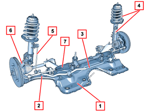
Key
1. Crossmember
2. Track control arm
3. Anti-roll bar
4. Spring-shock absorber assembly
5. Anti-roll bar joint
6. Steering knuckle
7. Steering box
The main components of the front suspension are:
-pressed steel track control arms (2 - Fig. 22).-front suspension crossmember (1) with high structural rigidity.-anti-roll bar (3) with connecting rods with spherical rods for mounting on the shock absorbers.-coil springs designed to improve thrust in order to reduce the forces on the shock absorber stem and consequently internal friction resulting in improved absorption of slight road imperfections.-special shock absorbers (4) with a spring, illustrated in Fig. 24, fitted inside to confer good lateral rigidity.Rear suspension
The system with semi-independent wheels with a torsion axle is also an excellent solution for the rear suspension on compact vehicles with front wheel drive, guaranteeing that not much space is taken up and, at the same time, offering a good compromise in terms of handling and comfort.
Fig. 23
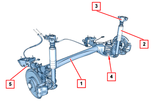
Key
1. Axle
2. Shock absorber
3. Shock absorber mounting
4. Spring
5. Bodyshell mounting flexible bush
The main components of the rear suspension on the MiTo are:
-torsion axle with C section (1 - Fig. 23) with excellent torsional rigidity and pressed side arms with two half casings-coil springs (4) with excellent rigidity to guarantee a sporty geometry-special shock absorbers (2) with a spring, illustrated in Fig. 24, fitted inside to confer good lateral rigidity.Special shock absorbers
These shock absorbers (Fig. 24) feature an internal spring (M) which acts during the extension in parallel to the main suspension spring with the main aim of reducing roll.
The internal spring (M) illustrated is located between the tube and the stem, secured to the upper end of the tube and acts on the shock absorber extension travel.
Fig. 24
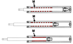
Fixing the length of the inner springs and the intervention point establishes the driving condition in which the springs start to work contributing to the overall rigidity of the vehicle geometry. These features ensure that in normal driving conditions the vehicle''s behaviour is conventional, whilst in sports driving conditions rigidity in the case of roll in increased with benefits in terms of handling.
In particular, the vehicle is fitted with special shock absorbers which, in the presence of strong lateral acceleration, behave in a similar way to a traditional vehicle with rigid suspension. In the case of low lateral acceleration, the springs inside the special shock absorbers do not intervene therefore, unlike a vehicle with rigid suspension, comfort is not adversely affected in non sports driving conditions.
Another feature that deserves to be mentioned is the fact that when the springs inside the special shock absorbers intervene when cornering, only the springs for the shock absorbers for the inner wheels are working (extended) and not those for the shock absorbers for the outer springs (compressed).
This feature leads to an asymmetrical rigidity configuration which alters the dynamics in the case of rolling, with two consequences:
-a more marked support on the outer wheels improving the grip of the tyres-a lowering of the roll centres resulting in improved stability.Wheel angle measurements
The figures given have been obtained in Standard A conditions, namely:
-with vehicle unladen with spare wheel, tools, accessories, supplies, full petrol tank and tyres inflated to the correct pressure.|
Front wheel toe in (total) |
-1 ± 1 mm |
|
Front wheel camber |
-27’ ± 20’ |
|
Front wheel caster |
3° 29’ ± 30’ |
|
Rear wheel camber |
- 1° ± 20’ |
|
Rear wheel toe in (total) |
1.7 ± 2 mm |
Wheels
Tyre inflation pressure when cold (bar)
|
Version |
Rim measurement |
Tyre measurement |
Pressures with medium load |
Pressures with heavy load | ||
|
Front |
Rear |
Front |
Rear | |||
|
1.4 petrol |
7J x 16 ET39 |
195/55 R16 87H |
2,3 |
2,1 |
2,3 |
2,3 |
|
7J x 16 ET39 |
205/45 R17 88W XL |
2,3 |
2,1 |
2,3 |
2,3 | |
|
7J x 16 ET39 |
215/45 R17 87W(*) |
2,2 |
2,1 |
2,3 |
2,3 | |
|
7.5J x 18 ET42 |
215/40 R18 89W XL (*) |
2,3 |
2,1 |
2,3 |
2,3 | |
|
1.4 Turbo Petrol |
7J x 16 ET39 |
195/55 R16 87H |
2,3 |
2,1 |
2,5 |
2,3 |
|
7J x 16 ET39 |
205/45 R17 88W XL |
2,4 |
2,2 |
2,8 |
2,5 | |
|
7J x 16 ET39 |
215/45 R17 87W XL (*) |
2,3 |
2,1 |
2,6 |
2,3 | |
|
7.5J x 18 ET42 |
215/40 R18 89W (*) |
2,4 |
2,2 |
2,7 |
2,4 | |
|
1.6JTDM |
7J x 16 ET39 |
195/55 R16 87H |
2,3 |
2,1 |
2,6 |
2,3 |
|
7J x 16 ET39 |
205/45 R17 88W XL |
2,6 |
2,2 |
2,8 |
2,3 | |
|
7J x 16 ET39 |
215/45 R17 87W(*) |
2,4 |
2,2 |
2,6 |
2,3 | |
|
7.5J x 18 ET42 |
215/40 R18 89W XL (*) |
2,5 |
2,2 |
2,7 |
2,3 | |
(*) Tyres which cannot be fitted with chains
| Remind the customer that: - On versions with 195/55 R16 and 205/45 R17 tyres, use smaller snow chains with a maximum projection of 9 mm beyond the tyre profile. - When the tyres are warm, the inflation pressure should be + 0.3 bar in relation to the recommended figure. However, recheck that the value is correct with the tyre cold. - With snow tyres the pressure figure should be +0.2 bar than the recommended value for the original tyres. |
Spare wheel: rim 135/70R16 - tyre 4B x 16ET15 - pressure 4.2 bar.
Tyre pressure monitoring system t.p.m.s.
(available on request for certain versions/markets)
The T.P.M.S. (Tyre Pressure Monitoring System) monitors the inflation of the tyres and notifies the customer of any irregular pressure conditions by a dedicated warning light in the instrument panel coming on.
This system consists of:
-four pressure sensors (one on each wheel) located inside the tyre on the wheel rim-a radiofrequency control unit located in the vehicle passenger compartment.The customer is notified about the tyre inflation status by means of a message in the multifunction display (where present).
Cruise control system
(available on request for certain versions/markets)
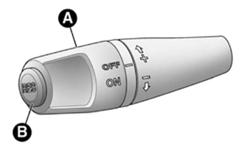
This is an electronically controlled driving assistance device that allows the vehicle speed that has been set (for speeds above 30 km/h) to be maintained irrespective of variations in driving conditions and the vehicle can be driven on long sections of straight, dry roads (e.g. motorways) at the desired speed without having to press the accelerator pedal.
Advise the customer to only switch the Cruise Control on in 5th speed or a higher gear and where the road conditions are such that the speed set can be safely maintained as follows:
-turn the ring nut (A - Fig. 25) to ON pressing the accelerator pedal-let the vehicle reach the desired speed-turn the ring nut (B) to (+) for at least a second, then release it: the vehicle speed remains memorized and the accelerator pedal can then be released.The device is automatically switched off in the following cases:
-if the ABS or VDC systems intervene-with the vehicle speed below the set limit-in the case of system failure.To restore the speed memorized, proceed as follows:
-accelerate gently until a speed close to that memorized is reached-engage the gear selected at the time the speed was memorized (5th speed or higher)-press button B.Fig. 25
Interior
Dashboard
The presence and position of the controls, instruments and gauges in the dashboard (Fig. 26) may vary depending on the version.
Fig. 26
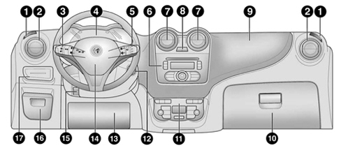
Key
1. Vent for directing air to the side windows
2. Adjustable and directable air vent
3. Exterior lights control lever
4. Instrument panel
5. Windscreen wiper/rearscreen wiper/trip computer control lever
6. Car radio (where fitted)
7. Adjustable and directable air vents
8. Hazard warning lights, door locking/unlocking button
9. Passenger front air bag
10. Oddments compartment
11. Heating/ventilation/climate control system controls
12. Starting device
13. Driver''s knee air bag (where fitted)
14. Driver''s front air bag
15. Steering wheel locking lever
16. Fuse box access flap
17. Panel with various controls
Display in instrument panel
(available on request for certain versions/markets)
Depending on the version, the instrument panel may be equipped with;
-multifunction display (on normal and sport versions) (Y - Fig. 27)-reconfigurable multifunction display (on normal and sport versions) (X - Fig. 27)Fig. 27
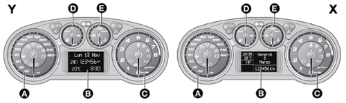
Key
A Speedometer
B Multifunction display
C Rev counter
D Fuel gauge with reserve warning light
E Engine coolant temperature gauge with overheating warning light
| Some warning lights are only present on Diesel versions. On diesel versions the end of scale for the rev counter is 6000 rpm |
Climate control systems
(available on request for certain versions/markets)
The MiTo has two different climate control systems:
-manual climate control-automatic dual zone climate control.Both systems distribute the air as illustrated in the diagram in Fig. 28.
Fig. 28
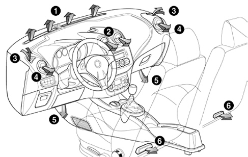
Key
1. Fixed upper diffuser
2. Directable centre diffusers
3. Fixed side diffusers
4. Directable side diffusers
5. Lower diffusers for front seats
6. Lower diffusers for rear seats
Dual zone automatic climate control system
The operating principle of the automatic climate control system is based on the control of the temperature linked to the "equivalent temperature" concept.
Therefore a climate control system that regulates the "equivalent temperature" does not work to keep the passenger compartment at a constant temperature, but to stabilize the thermal conditions felt by the customer.
The thermal sensation depends on all the thermal energy exchanges with the environment and is estimated on the basis of ambient parameters.
There is a sensor to detect solar rays with acquisition of the bilateral signal (left and right) that allows the software to adapt the comfort in the passenger compartment depending on the sun''s rays intervening to adjust the temperature in a differentiated manner on each side (driver and passenger).
It is therefore necessary to explain to the customer that it is not necessarily the temperature measured in the passenger compartment using a thermometer that should coincide with the one shown in the display because the thermometer indicates degrees centigrade, the display shows a temperature measured in equivalent temperature degrees which is an indicator of climate comfort.
Remind the customer that the only possible action is to identify and select an equivalent temperature value (using the buttons shown in Fig. 29) that is to their satisfaction and the system will work by regulating all the variables in its control to ensure the required thermal sensation.
Fig. 29
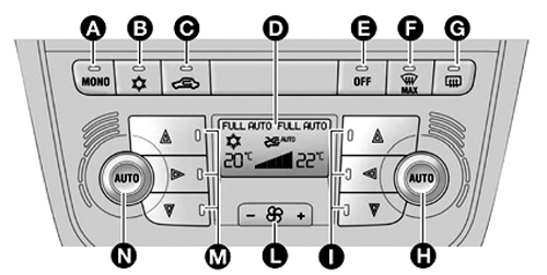
Key
A MONO function button (set temperature alignment) driver/passenger side;
B climate control compressor on/off button;
C interior air recirculation on/off button;
D display;
E climate control off button;
F MAX DEF function activation button (rapid defrosting/demisting of front windows);
G heated rear windscreen on/off button;
H AUTO function activation button (automatic operation) and passenger side temperature adjustment knob
I passenger side air distribution selection button;
L fan speed increase/decrease;
M driver''s side air distribution selection button;
N AUTO function activation button (automatic operation) and driver''s temperature adjustment knob.
Air bag
The new MiTo may be fitted with an electronically controlled Air Bag system which, in the case of a front or side impact of a certain magnitude, controls the partial or total activation of the various safety devices.
All vehicles may be fitted, as standard or on request, with the following Air Bags:
-Driver''s front air bag in the centre of the steering wheel-Passenger front air bag in the top part of the dashboard-Driver''s knee bag in the middle underneath the steering wheel;-Side Bags, protecting the chest, in the front seat backrests-Window Bags behind the roof side trims.Seats
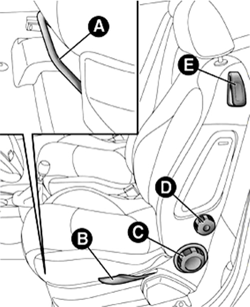
Manually adjusted front seats (Fig. 30)
The front seats can, depending on the adjustments, assume different configurations; the main ones are described below:
-lengthwise adjustment (A)-height adjustment (B)-backrest angle adjustment (C)-lumbar adjustment (D - where available)-backrest folding (E)-heating (available on request for certain versions/markets).Fig. 30
Sun roof
(available on request for certain versions/markets)
The extensive glazed sun roof is composed of two glass panels, one fixed and one moving, with two manually operated sun blinds (front and rear).
The sun roof can only be operated with the ignition key in the ON position.
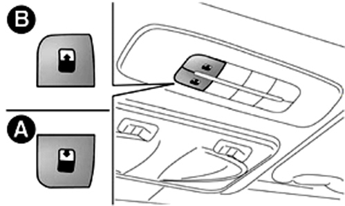
The controls A and B (Fig. 31) in the dedicated panel near the front courtesy light, operate the sun roof opening/closing functions.
Fig. 31
Sun roof initialization procedure
See the Operations in the Network paragraph
Emergency manoeuvre
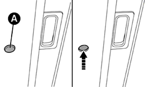
It should be remembered that, if the button (A - Fig. 32) fails to work, the sun roof can be manoeuvred manually as follows:
-remove the cap (A) located on the inner trim, between the two sun blinds;-take the spanner from the tool box (in the luggage compartment);-introduce the spanner in the housing for cap A that has been removed and turn it:-clockwise, to open the roof;-anti-clockwise, to close the roof.Fig. 32
Anti-crush safety device
(available on request for certain versions/markets)
The sun roof has an anti-crush safety system capable of detecting the presence of an object whilst the roof is closing; when this happens the system stops and the glass travel is immediately reversed.
Electric windows
Anti-crush safety device
(available on request for certain versions/markets)
The electric windows also have an anti-crush safety system when the windows are closing.
There is an anti-crush safety sensor on the upper seal of each of the doors which reverses the movement of the window any time an obstacle (e.g. a finger, hand, etc.) is detected between the glass and the actual seal, thereby preventing accidental crushing.
The anti-crush safety function is activated both during the manual and the automatic operation of the window. After the activation of the anti-crush safety system the travel of the glass is immediately interrupted and reversed until it is in the lower end of travel position.
The window cannot be operated in any way during this time.
| If the anti-crush protection intervenes 5 consecutive times within a minute or is faulty, the automatic closing operation of the window is inhibited, only allowing it in steps of half a second the button is released for the subsequent manoeuvre. In order to restore the correct operation of the system, one of the following manoeuvres must be performed: - switching the engine off and starting it; - a downwards movement of the window involved. |
| It should be remembered that with the ignition key OFF or extracted, the electric windows remain activated for about 3 minutes and are immediately deactivated when one of the doors is opened. On some versions, pressing the button (open padlock symbol) on the remote control for more than 2 seconds opens the windows, whilst pressing the button (closed padlock symbol) for more than 2 seconds closes the windows. |
Rear light clusters and brake lights
The MiTo features innovative LED technology (Light Emitting Diodes) to ensure the main functions of the rear light cluster illustrated in Fig. 33.
Fig. 33
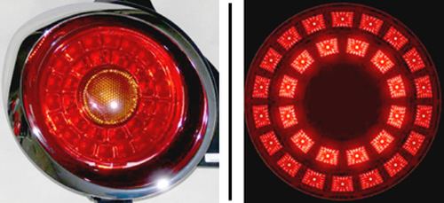
In addition to advantages in terms of compactness and lightness, this technology features low energy consumption combined with very efficient brightness.
The LEDs consume up to 60% less than traditional bulbs and do not become hot, exactly the opposite of incandescent bulbs which dissipate most energy in heat.
As they do not have a classic filament, which is easily broken, they are shock-resistant to vibrations with a life of about 100,000 hours of operation compared with 3-5,000 hours for regular bulbs.
To this we must add improved visibility and more rapid response times for the brake lights coming on.
The LEDs turn on more quickly: 1 thousandth of a second rather than 200. This feature means that the vehicle behind sees that braking is taking place eariler (gaining a distance of about 5 metres at 120 km/h).
Alcohol tester kit
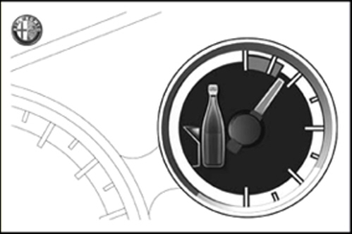
Another new feature on the Mito is the Alcohol Tester Kit located in the passenger side glove compartment.
The kit consists of an envelope, illustrated in Fig. 34, containing all the medical products for checking alcohol levels. The envelope also contains instructions for the correct use of the kit.
| remind the customer that, like all medical products, the kit has an expiry date and therefore needs replacing when the contents are past their date. |
Fig. 34
Telematic system
(available on request for certain versions/markets)
Various preparation systems are available for the MiTo designed to cover all requirements, namely:
-Audio systems preparation-Car radio/CD and Car radio/CD with Mp3 preparation-Blue&Me™: hands-free system with bluetooth® sms message reader and multimedia player-Blue&Me™ Nav: hands-free system with bluetooth® sms message reader, multimedia player and navigation systemAudio systems technical specifications
(available on request for certain versions/markets)
Standard audio sources are available (radio tuner, audio CD/MP3).
The acoustic system for the vehicle comes in three distinct levels:
-Standard level audio system-Medium level audio system-Bose Hi-Fi level audio system.Power: The maximum output power is 4x40W
Standard level audio system
Front speakers
-2 x 38 mm diameter tweeters;-2 x 165 mm diameter mid-woofer speakers.Rear speakers
-2 x 165 mm diameter full-range speakers.Medium level radio (dual tuner)
Medium level audio system
Front speakers
-2 x 38 mm diameter tweeters;-2 x 165 mm diameter mid-woofer speakers.Rear speakers
-2 x 38 mm diameter tweeters;-2 x 165 mm diameter mid-woofer speakers.Top of the range radio (dual tuner and double aerial)
Bose Hi-Fi level audio system
Front speakers
-2 x 38 mm diameter tweeters;-2 x 165 mm diameter mid-woofer speakers.Rear speakers
-2 x 38 mm diameter tweeters;-2 x 165 mm diameter mid-woofer speakers;-1 x 8 channel amplifier;-1 bass box.Top of the range radio (dual tuner and double aerial)
Radio
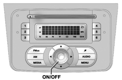
There are two versions: car radio CD and car radio CD and mp3 illustrated in Fig. 35. Both versions have a painted front section.
Fig. 35 - Car radio CD (Version with mp3)
Blue & me
The telematic solution for cars based on Windows mobile™ is the answer, on the MiTo, to increasing market demands for systems that allow the use of personal devices such as mobile phones on board the vehicle, whilst at the same time protecting the safety of the user and making the latest generation multimedia services available.
The system proposed is known as Blue&Me™ and it is incorporated in the vehicle dashboard. There are 2 levels of Blue&Me™ available:
-Blue&Me™: hands-free system with bluetooth® sms message reader and multimedia player-Blue&Me™ Nav: hands-free system with bluetooth® sms message reader, multimedia player and navigation systemOPERATIONS IN NETWORK
-For the routine P.D.I. operations, refer to Service News 00.11.08 - CD 03/2008.-For the Planned Maintenance Programme refer to Service news 00.12.08 - CD 03/2008-For general information, technical data, descriptions and operation, fault diagnosis, tests, repair procedures and wiring diagrams, refer to the Service Manual.-For the fault diagnosis of the electronic systems equipped with auto diagnosis, use the Examiner updated with the new programme release 7.50 or higher.For all operations that involve disconnecting the battery, e.g.:
-no control unit power supply-replacing the sun roof/electric window protective fuses-replacing sun roof/electric window components.-the initialization procedure described below must be carried out:sun roof initialization procedure
-place the roof in the closed position;-keep the button pressed to allow the roof to close completely in stages;-wait until the roof is completely closed and the electric motor has stopped.electric windows system initialization procedure
-place the window to be initialized in a closed position (upper end of travel position);-rafter the window has reached the upper end of travel, hold the up button pressed for at least one second. | On certain versions/markets, after there has been no power supply for the control units (battery replaced or disconnected or protective fuses for the electric window control units replaced), the automatic operation of the actual windows should be restored as follows: 1. Fully lower the driver''s door window keeping the button pressed for at least 3 seconds after the lower end of travel position has been reached. 2. Fully raise the driver''s door window keeping the button pressed for at least 3 seconds after the upper end of travel position has been reached. 3. Proceed in the same way described in points 1 and 2 for the passenger door. 4. Make sure that the initialization is correct by checking that the windows work automatically. |
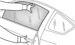
| With the central locking on, pulling the interior opening lever for one of the doors switches the locking off for all the doors. If there is no electric power supply (fuse blown, battery disconnected, etc.) it is still possible to operate the door locking manually; in this case the automatic lowering function for the windows is not available and to open or close the door with the window closed it is necessary to exert pressure on the window towards the inside of the vehicle (Fig. 36) to facilitate the movement of the window on the moulding. |
Fig. 36