
 Removing
(
Refitting
Removing
(
Refitting )
)
- To remove the pedal support, remove the dashboard trim, thus refer to
|
|
Removing
(
Refitting
)
- To remove the pedal support, remove the dashboard trim, thus refer to |
|
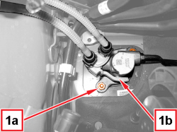  |
1. Undo the nuts (1a) fixing the master cylinder (1b) to the brake servo. |
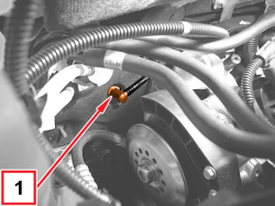  |
1. Prise up and remove the vacuum pipe connector from the brake servo. |
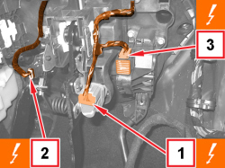  |
1. Disconnect the electrical connection for the brake pedal switch.
2. Disconnect the electrical connection for the clutch pedal switch.
3. Detach the electrical connection for the accelerator pedal.
|
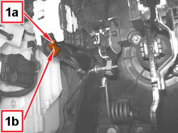  |
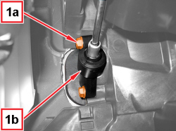
1. Remove the clip (1a) and the pin (1b) connecting the clutch pump fork to the pedal. |
  |
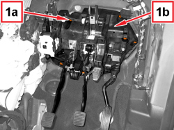
1. Undo the screws (1a) and move the clutch pump (1b) to one side. |
  |
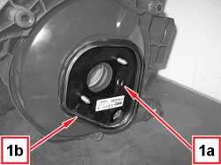
1. Undo the fastenings (1a) and remove the pedal support (1b) complete with brake servo. |
  |
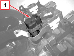
1. Remove the flange (1a) with gasket (1b). |
  |
1. Release the brake pedal switch from the pedal support rotating it clockwise towards the accelerator pedal. |
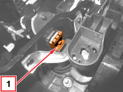  |
1. Remove the retaining clip and move back the pin connecting the brake servo fork to the brake pedal. |
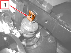  |
1. Remove the retaining clip and move back the pin connecting the brake servo fork to the brake pedal. |
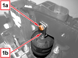  |
1. Remove the pin (1a) connecting the brake servo fork (1b) to the brake pedal. |
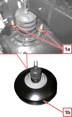  |
1. Undo the nuts (1a) and remove the brake servo (1b) from the pedal mounting. |
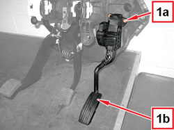  |
1. Undo the screws (1a) and remove the accelerator pedal (1b). |
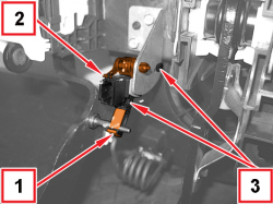  |
1. Retract the (yellow) clip for clutch pedal pin. 2. Rotate the fastening lever and take it partially out from its housing. 3. Remove the clutch pedal switch from its mounting releasing the fastening pin. |
|
|
Refitting
(
Removing
)
|
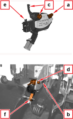  |
- Place the clutch pedal switch in its housing engaging the fastening tooth (a) in the suitable slot (b) of pedal support. - Slightly move the clutch pedal switch so that it positions correctly on the laying plane with the fastening lever (c) in the hole (d). - Rotate by 90° clockwise the fastening lever (c) until coupling it in the suitable housing (e).
- Use the locking clip (f) to engage the clutch pedal pin in the switch swinging lever. |
|
|
- Place the accelerator pedal back in its housing and tighten the screws. |
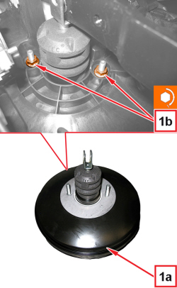  |
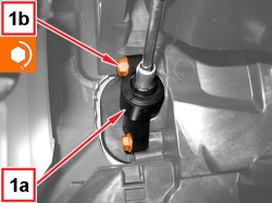
1. Place the brake servo (1a) in its housing and tighten the nuts (1b) to the prescribed torque.
|
|
|
- Connect the brake servo fork to the brake pedal using the pin and engage the retaining clips. - Place the brake servo flange in its housing, with relevant gasket. - Refit the pedal mounting complete with brake servo and tighten the fastenings. |
  |
1. Position the clutch pump (1a) in its housing and tighten the screws (1b) to the prescribed torque.
|
|
|
- Connect the clutch pump fork to the pedal using the pin and engage the retaining clip. |
|
|
- Lock the brake pedal in position with a suitable support. - Place the brake pedal switch in its housing by rotating it 45° towards the clutch pedal, until it clicks to engage.
|
|
|
- Secure the electrical connection for the accelerator pedal. - Connect the electrical connection for the brake pedal switch. - Connect the electrical connection for the clutch pedal switch. - Connect the vacuum pipe connector to the brake servo. |
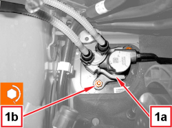  |
1. Place the master cylinder (1a) in its housing and tighten the nuts (1b) to the prescribed torque.
|
|
|
- Assemble the dashboard trim with reference to |
|
|
|
- Remove the brake pedal locking mounting and test stop light operation. |
|
|
- Secure the electrical connection for the accelerator pedal. - Connect the electrical connection for the brake pedal switch. - Connect the electrical connection for the clutch pedal switch. - Connect the vacuum pipe connector to the brake servo. |
