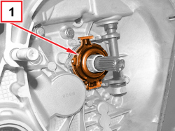
|
 Removing
(
Refitting Removing
(
Refitting )
)
 | The two overhaul procedures of the C510.5 gearbox are described below. The first one is valid until 04/2012 the second one from 04/2012. |
|

|
- Release the gearbox and differential from the support tool used for removing/refitting from the vehicle.
|
1860873000 |
Gearbox support |
Removing/refitting gearbox from the vehicle |
1.4 8v 1.4 16v TJet 120 HP 1.4 Turbo MultiAir (5 SPEEDS) 1.3 MultiJet 85/95 HP |
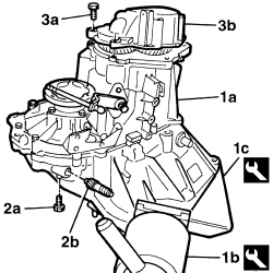
1. Fit the gearbox and differential (1a) on the overhaul stand (1b) using tool (1c).
|
|
Two operators are needed for this operation.
|
|
1871000000 |
Rotating stand |
Gearbox overhaul |
1.4 8v 1.4 16v TJet 120 HP 1.4 Turbo MultiAir (5 SPEEDS) 1.3 MultiJet 85/95 HP |
|
1871001014 |
Gearbox support |
Gearbox overhaul |
|
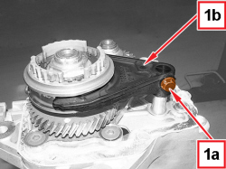
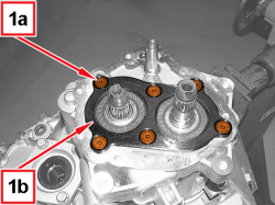
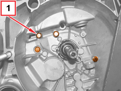
2. Undo the screw (2a) and remove the odometer idler gear (2b).
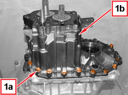
3. Undo the screws (3a) and remove rear cover (3b).
|
|
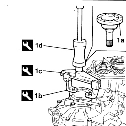
1. Remove the left differential internal driveshaft (1a) using the tool comprising the brackets (1b), the strut (1c) and the mallet (1d).
|
1840005308 |
Brackets |
Removing differential left inner driveshaft |
1.4 16v TJet 120 HP 1.4 Turbo MultiAir (5 SPEEDS) 1.3 MultiJet 85/95 HP |
|
1840005001 |
Steering knuckle |
Differential inner driveshafts removal Removing bearings/hobs/main shaft-layshaft |
1.4 8v 1.4 16v TJet 120 HP 1.4 Turbo MultiAir (5 SPEEDS) 1.3 MultiJet 85/95 HP |
|
1840206000 |
Mallet |
Removing differential left inner driveshaft |
1.4 16v TJet 120 HP 1.4 Turbo MultiAir (5 SPEEDS) 1.3 MultiJet 85/95 HP |
|
|
- Engage any gear using the gear selection/engagement lever.
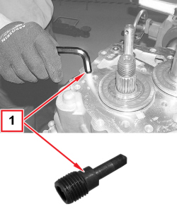
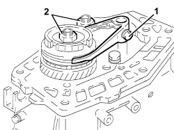
1. Undo the screw fixing the 5th speed fork to the main shaft.
- Engage the 5th speed by pressing the fork on the main shaft.
|
|
If two gears are engaged simultaneously the gear shafts will lock.
|
2. Straighten the staking and loosen the ring nuts for the main and layshafts.
- Place the 5th speed control fork in neutral.
|
|
The positioning of the 5th speed control fork in neutral is necessary to prevent the synchronizer rollers from being lost.
|
|
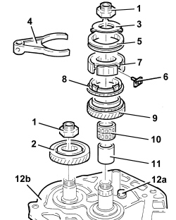
|
1. Completely undo the ring nuts for the main and layshafts.
2. Remove the 5th speed driven gear.
3. Remove the 5th speed synchronizer rollers and springs retaining flange.
4. Remove the 5th speed control fork.
5. Remove the 5th speed engagement sliding sleeve.
6. Remove the pre-synchronizer mountings.
7. Remove the 5th speed engagement sliding sleeve hub.
8. Remove the 5th speed synchroniser ring.
9. Remove the 5th speed drive gear.
10. Remove the needle bearing for the 5th speed drive gear.
11. Remove the 5th speed drive gear bush.
12. Undo the screw (12a) and remove the main and layshaft rear bearing retaining plate (12b).
|
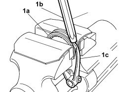
|
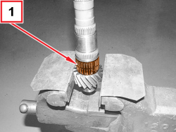
1. Lock the sleeve (1a) in the vice fitted with protective plates, then use a brass drift (1b) alternately on the two ends of fork (1c) until it is released from the sleeve.

|
Take care not to nick the tapered part of the sleeve and the ends of the fork with the drift.
|
|
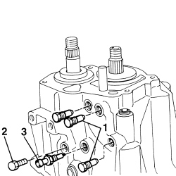
|
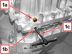
1. Undo the plugs for positioning the gear control rods.
2. Undo the reverse shaft securing screw.
3. Unscrew the reverse light switch.
|
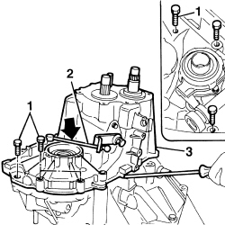
|
1. Undo the screws securing the gearbox casing to the manual gearbox bellhousing.
2. Position the gear selector/engagement lever downwards.
3. Remove the gearbox casing using two screwdrivers for leverage by the special projections.
|
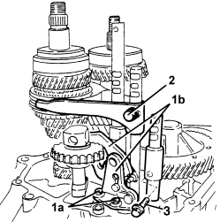
|
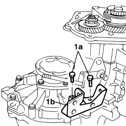
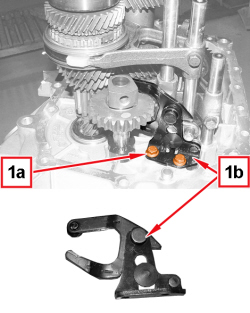
1. Undo the screws (1a) and remove the reverse fork mounting bracket (1b).
2. Undo the 3rd-4th speed fork screw.
3. Undo the 1st-2nd speed drive fork screw.
|
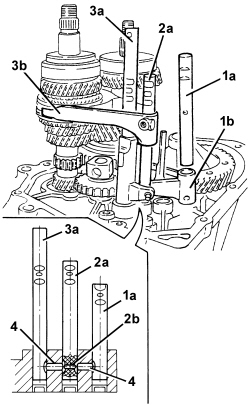
|
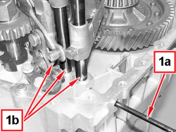
1. Remove the 1st-2nd speed drive rod (1a) together with fork (1b).
|
|
If the rod offers resistance during the extraction, the other rods (2a) and (3a) must be adjusted to move the selectors (4) and (2b).
|
2. Remove the 3rd-4th speed drive rod (2a).
|
|
Work carefully to prevent pawl (2b) from accidentally coming out.
|
3. Simultaneously remove the 5th-reverse gear drive rod (3a) and 3rd-4th speed fork (3b).
4. Remove the two gear engagement safety dogs.
|
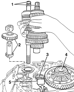
|
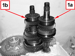
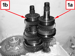
1. Remove the main and layshaft assemblies at the same time.
2. Remove the reverse idler gear.
3. Remove the layshaft front bearing.
4. Remove the differential assembly.
5. Remove the magnet.
|
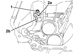
|
1. Undo the gear control dog screw.
2. Remove the pin (2a) using a suitable drift and remove the gear control dog (2b).
|
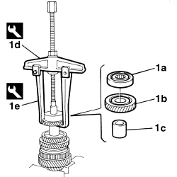
|
- Proceed with dismantling the layshaft following the instructions given below. 1. Remove the rear bearing (1a), the 4th speed driven gear (1b) and the spacer between 3rd and 4th speeds (1c) using the tools (1d) and (1e). |
|
1840005002 |
Extractor |
Removing layshaft rear bearing Removing layshaft front bearing |
1.4 8v 1.4 16v TJet 120 HP 1.4 Turbo MultiAir (5 SPEEDS) 1.3 MultiJet 85/95 HP |
|
|
1840005303 |
Hooks |
Differential inner driveshafts removal Removing layshaft rear bearing Removing 3rd speed driven gear and 2nd speed driven gear Removing 3rd and 4th speed engagement sliding sleeve hub, synchroniser ring and 3rd speed drive gear |
1.4 8v 1.4 16v TJet 120 HP 1.4 Turbo MultiAir (5 SPEEDS) 1.3 MultiJet 85/95 HP |
|
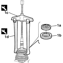
|
1. Remove the 3rd speed driven gear (1a) and the 2nd speed driven gear (1b) using the tools (1c) and (1d).
|
1840005002 |
Extractor |
Removing layshaft rear bearing Removing layshaft front bearing |
1.4 8v 1.4 16v TJet 120 HP 1.4 Turbo MultiAir (5 SPEEDS) 1.3 MultiJet 85/95 HP |
|
1840005306 |
Hooks |
Removing 1st, 2nd and 3rd speed driven gears Dismantling main shaft Removing layshaft front bearing |
1.4 8v 1.4 16v TJet 120 HP 1.4 Turbo MultiAir (5 SPEEDS) 1.3 MultiJet 85/95 HP |
|
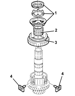
|
1. Remove the 2nd speed double cone synchronizer assembly.
2. Remove the needle bearing for the 2nd speed driven gear.
3. Remove the 1st-2nd and reverse engagement sliding sleeve.
4. Remove the pre-synchronizer mountings.
|
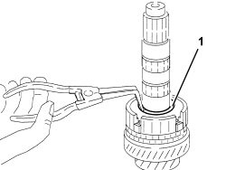
|
1. Remove the retaining ring for the first-second speed and reverse sliding sleeve hub using suitable pliers.
|
|
When refitting, replace the retaining circlip.
|
|
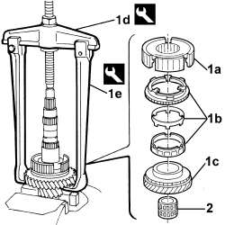
|
1. Remove the 1st-2nd and reverse sliding sleeve hub (1a), the 1st speed synchroniser ring assembly (1b) and 1st speed driven gear (1c) using tools (1d) and (1e).
|
1840005002 |
Extractor |
Removing layshaft rear bearing Removing layshaft front bearing |
1.4 8v 1.4 16v TJet 120 HP 1.4 Turbo MultiAir (5 SPEEDS) 1.3 MultiJet 85/95 HP |
|
1840005306 |
Hooks |
Removing 1st, 2nd and 3rd speed driven gears Dismantling main shaft Removing layshaft front bearing |
1.4 8v 1.4 16v TJet 120 HP 1.4 Turbo MultiAir (5 SPEEDS) 1.3 MultiJet 85/95 HP |
2. Remove the needle bearing.
|
|
The layshaft front bearing inner race cannot be removed; if necessary, replace it together with the layshaft.
|
|
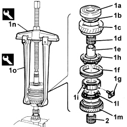
|
- Proceed with dismantling the main shaft following the instructions given below.
1. Remove the rear bearing (1a), the shim (1b), the 4th speed drive gear (1c), the 4th speed drive gear needle bearing (1d), the 4th speed drive gear bush (1e), the 3rd and 4th speed sliding sleeve (1f), the presynchroniser pads (1g) for the 3rd and 4th speed sliding sleeve hub, the 4th speed synchroniser ring (1h), the hub for the 3rd and 4th speed sliding sleeve (1i), the 3rd speed synchroniser ring (1l) and the 3rd speed drive gear (1m) using the tools (1n) and (1o).
|
1840005002 |
Extractor |
Removing layshaft rear bearing Removing layshaft front bearing |
1.4 8v 1.4 16v TJet 120 HP 1.4 Turbo MultiAir (5 SPEEDS) 1.3 MultiJet 85/95 HP |
|
1840005306 |
Hooks |
Removing 1st, 2nd and 3rd speed driven gears Dismantling main shaft Removing layshaft front bearing |
1.4 8v 1.4 16v TJet 120 HP 1.4 Turbo MultiAir (5 SPEEDS) 1.3 MultiJet 85/95 HP |
2. Remove the needle bearing for the 3rd speed drive gear.
|
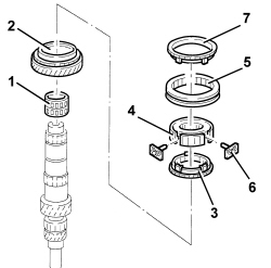
|
Refitting
(
Removing
)
- Proceed with washing and checking the condition of all the components. - Proceed with reassembling the main shaft following the instructions given below. 1. Fit the needle bearing for the 3rd speed drive gear. 2. Fit the 3rd speed drive gear. 3. Fit the 3rd speed synchroniser ring. 4. Fit the 3rd and 4th speed sliding engagement sleeve hub. 5. Fit the 3rd and 4th speed sliding engagement sleeve. 6. Fit the pre-synchronizer mountings in their housings in the sliding sleeve hub. 7. Fit the 4th speed synchroniser ring. |
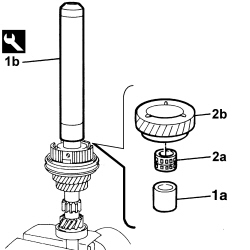
|
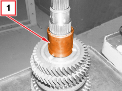
1. Fit the bush for 4th speed drive gear (1a) using the tool (1b).
|
1860945000 |
Fitting tool |
Fitting 4th speed drive gear bush/main shaft rear and front bearing/1st and 2nd speed sliding sleeve hub |
1.4 8v 1.4 16v TJet 1.4 16v 1.6 JTD 16v 1.3 MultiJet 1.4 MultiAir 1.4 Turbo MultiAir 0.9 TwinAir |
2. Fit the roller bearing for 4th speed drive gear (2a) and the 4th speed drive gear (2b).
|
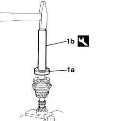
|
1. Fit the rear bearing (1a) using tool (1b).
|
1860945000 |
Fitting tool |
Fitting 4th speed drive gear bush/main shaft rear and front bearing/1st and 2nd speed sliding sleeve hub |
1.4 8v 1.4 16v TJet 1.4 16v 1.6 JTD 16v 1.3 MultiJet 1.4 MultiAir 1.4 Turbo MultiAir 0.9 TwinAir |
|
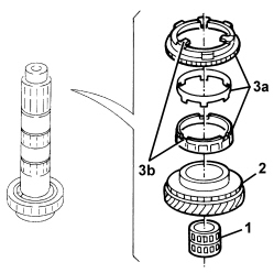
|
- Proceed with reassembly of the layshaft following the instructions given below.
1. Fit the needle bearing for the 1st speed driven gear.
2. Fit the 1st speed driven gear.
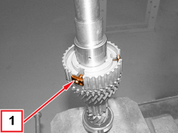
3. Fit the three 1st speed synchronizer rings (3a), aligning the fastenings (3b).
|
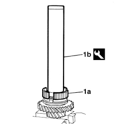
|
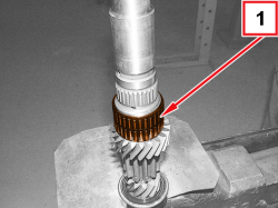
1. Fit the hub for the 1st and 2nd speed sliding sleeve using tool (1b).
|
1860945000 |
Fitting tool |
Fitting 4th speed drive gear bush/main shaft rear and front bearing/1st and 2nd speed sliding sleeve hub |
1.4 8v 1.4 16v TJet 1.4 16v 1.6 JTD 16v 1.3 MultiJet 1.4 MultiAir 1.4 Turbo MultiAir 0.9 TwinAir |
|
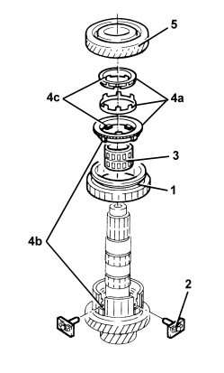
|
- Fit a new 1st and 2nd speed sliding sleeve hub retaining ring.
1. Fit the 1st-2nd and reverse engagement sliding sleeve.
2. Refit the pre-synchronizer mountings in their housings in the 1st-2nd speed and reverse sliding sleeve hub.
3. Fit the needle bearing for the 2nd speed driven gear.
4. Fit the three 2nd speed synchronizer rings (4a), aligning fastenings (4b) and (4c).
5. Fit the 2nd speed driven gear.
|
|
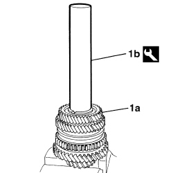
1. Fit the 3rd speed driven gear (1a) using tool (1b).
|
1870465000 |
Fitting tool |
Fitting 3rd speed driven gear/4th speed driven gear Fitting layshaft rear bearing |
1.4 16v TJet 120 HP 1.4 Turbo MultiAir (5 SPEEDS) 1.3 MultiJet 85/95 HP |
|
|
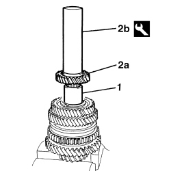
1. Fit the spacer between the 3rd speed driven gear and the 4th speed driven gear.
2. Fit the 4th speed driven gear (2a) using tool (2b).
|
1870465000 |
Fitting tool |
Fitting 3rd speed driven gear/4th speed driven gear Fitting layshaft rear bearing |
1.4 16v TJet 120 HP 1.4 Turbo MultiAir (5 SPEEDS) 1.3 MultiJet 85/95 HP |
|
|
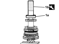
1. Fit the rear bearing (1a) using tool (1b).
|
1870448000 |
Fitting tool |
Fitting layshaft rear bearing Fitting layshaft front bearing inner race |
1.4 16v TJet 120 HP 1.4 Turbo MultiAir (5 SPEEDS) 1.3 MultiJet 85/95 HP |
|
|
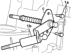
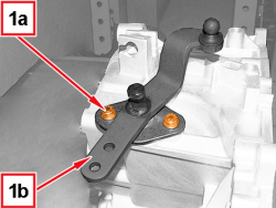
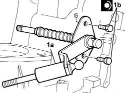
1. Fit the gear selector/engagement lever (1a) and secure it by tightening screws (1b) to the prescribed torque.
|
Gear selection/engagement lever |
Screw |
M8 |
2.1 ÷ 2.6 |
1.4 16v TJet 120 HP 1.4 Turbo MultiAir (5 SPEEDS) 1.3 MultiJet 85/95 HP |
|
|
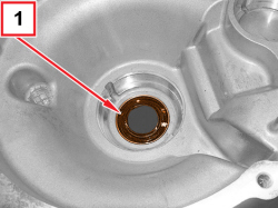
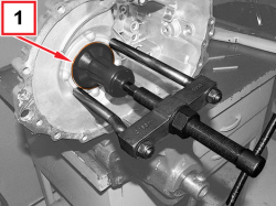
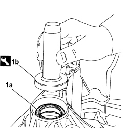
1. Fit a new engine side oil seal (1a) for the manual gearbox bellhousing using the tool (1b).
|
1875016000 |
Fitting tool |
Fitting differential right shaft oil seal Fitting engine side oil seal for manual gearbox to engine support Fitting differential flange oil seal |
1.4 8v 1.4 16v 1.4 16v TJet 120 HP 1.4 MultiAir 1.4 Turbo MultiAir (5 SPEEDS) 1.3 MultiJet 85/95 HP 0.9 TwinAir |
|
|
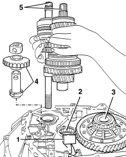
1. Fit the magnet.
2. Fit the layshaft front bearing.
3. Fit the differential assembly.
4. Fit the reverse idler gear.
|
|
Make sure that the gear engagement teeth are facing downwards.
|
5. Fit the main and layshaft assemblies at the same time.
- Fit the gear engagement safety pawls using a suitable drift.
|
|
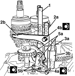
1. Fit the 5th speed and reverse drive rod.
2. Fit the 3rd - 4th speed control fork (2a) and control rod (2b).
|
|
Place the safety pawl on the rod before fitting it in its housing.
|
3. Fit the 1st-2nd speed drive rod (3a) together with fork (3b).
|
|
To facilitate installation, move the 1st-2nd speed control rod in the arrowed direction.
|
4. Tighten the screws securing 1st-2nd speed control forks (4a) and 3rd-4th speed control forks (4b) to the prescribed torque.
|
1st and 2nd speed control fork |
Screw |
M6 |
1.5 ÷ 1.9 |
1.4 16v TJet 120 HP 1.4 Turbo MultiAir (5 SPEEDS) 1.3 MultiJet 85/95 HP |
|
3rd and 4th speed control fork |
Screw |
M6 |
1.5 ÷ 1.9 |
1.4 16v TJet 120 HP 1.4 Turbo MultiAir (5 SPEEDS) 1.3 MultiJet 85/95 HP |
5. Fit the reverse control fork mounting bracket (5a) and secure it by tightening the screws (5b) to the prescribed torque.
|
Reverse control fork mounting bracket |
Screw |
M6 |
8.5 ÷ 11.1 |
1.4 16v TJet 120 HP 1.4 Turbo MultiAir (5 SPEEDS) 1.3 MultiJet 85/95 HP |
|
|
- Place all the gear control forks in neutral.
- Apply sealant to the contact surfaces between the manual gearbox bellhousing and the gearbox casing.
- Fit the gearbox casing on the manual gearbox bellhousing.
|
|
Keep the gear selector/engagement lever upwards and check that the gear selection dog engages in the 3rd-4th speed control fork.
|
- Tighten the gearbox casing screws to torque.
|
Gearbox casing |
Screw |
M8 |
2.1 ÷ 2.6 |
1.4 16v TJet 120 HP 1.4 Turbo MultiAir (5 SPEEDS) 1.3 MultiJet 85/95 HP |
- Fit the gear control rod positioning plugs.
- Tighten the reverse shaft screw to the prescribed torque.
|
Reverse shaft |
Screw |
M8 |
2.9 ÷ 3.6 |
1.4 16v TJet 120 HP 1.4 Turbo MultiAir (5 SPEEDS) 1.3 MultiJet 85/95 HP |
- Fit the reverse light switch.
- Fit the main and layshaft rear bearing retaining rings.
|
|
Position the retaining rings with their openings at the front to facilitate fitting.
|
- Apply sealant to the contact surfaces between the gearbox casing and the main and layshaft rear bearing retaining plate.
- Fit the main and layshaft rear bearing retaining plate and secure it by tightening the screw to the prescribed torque.
|
Main and layshaft rear bearing retaining plate |
Screw |
M8 |
2.1 ÷ 2.6 |
1.4 16v TJet 120 HP 1.4 Turbo MultiAir (5 SPEEDS) 1.3 MultiJet 85/95 HP |
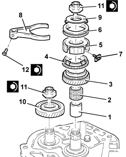
1. Fit the 5th speed drive gear bush.
2. Fit the needle bearing for the 5th speed drive gear.
3. Fit the 5th speed drive gear.
4. Fit the 5th speed synchroniser gear.
5. Fit the 5th speed engagement sliding sleeve hub.
6. Fit the 5th speed engagement sliding sleeve.
7. Place the pre-synchronizer mountings in their housings.
8. Fit the 5th speed control fork.
9. Fit the 5th speed synchronizer rollers and springs retaining flange.
10. Fit the 5th speed driven gear.
11. Tighten the new ring nuts for the main and layshafts to the prescribed torque.
|
Main and layshaft ring nuts |
Ring nut |
M20 |
10 ÷ 12.4 |
1.4 16v TJet 120 HP 1.4 Turbo MultiAir (5 SPEEDS) 1.3 MultiJet 85/95 HP |
12. Tighten the screw for the 5th speed control fork to the prescribed torque.
|
5th speed control fork |
Screw |
M6 |
1.5 ÷ 1.9 |
1.4 16v TJet 120 HP 1.4 Turbo MultiAir (5 SPEEDS) 1.3 MultiJet 85/95 HP |
|
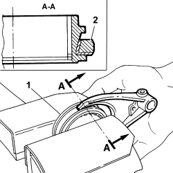
|
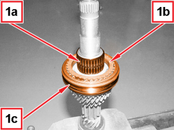
1. Lock the sleeve in a vice fitted with protective plates;
2. Position the fork so that the tapered part is in the same direction as that of the sleeve, resting it against the shoulder on the side where the sleeve diameter is smaller;
- fit the fork manually, exerting the necessary pressure, until it is completely inserted in the sleeve.
|
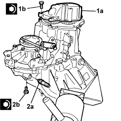
|
|
|
When the fitting is complete, check that the sleeve can rotate freely inside the fork.
|
- Apply sealant to the contact surfaces between the main and layshaft rear bearing retaining plate and the rear cover.
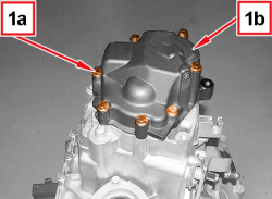
1. Fit the rear cover (1a) and secure it by tightening the screws (1b) to the prescribed torque.
|
Rear cover |
Screw |
M8 |
2.1 ÷ 2.6 |
1.4 16v TJet 120 HP 1.4 Turbo MultiAir (5 SPEEDS) 1.3 MultiJet 85/95 HP |
2. Fit the odometer idler gear (2a) and secure it with the screw (2b).
|
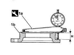
|
1. Position the tool (1a), complete with dial gauge, on the differential flange (1b) and measure distance "H" (flange height).
|
1895655000 |
Mount |
Determining thickness of differential bearing scraper ring |
1.4 8v 1.4 16v 1.4 16v TJet 120 HP 1.4 MultiAir 1.4 Turbo MultiAir (5 SPEEDS) 0.9 TwinAir 1.3 MultiJet 85/95 HP |
|
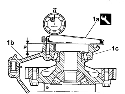
|
1. Position the tool (1a) complete with dial gauge on differential flange support surface (1b) and measure distance "P" (depth between differential flange support surface and bearing (1c) outer race).
|
1895655000 |
Mount |
Determining thickness of differential bearing scraper ring |
1.4 8v 1.4 16v 1.4 16v TJet 120 HP 1.4 MultiAir 1.4 Turbo MultiAir (5 SPEEDS) 0.9 TwinAir 1.3 MultiJet 85/95 HP |
|
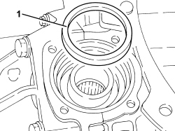
|
- Calculate the thickness "S" of the differential bearing pre-loading thrust ring, using the following formula:
S = P - H + 0.12
|
|
0.12 corresponds to the prescribed interference for the bedding in and pre-loading of the differential bearings.
After determining the exact thickness of the thrust ring, try to pick a ring as close to this thickness as possible from the spares provided. If you cannot make up the exact thickness using one or more of the adjustment rings available, fit the next size/s up.
|
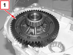
1. Place the differential bearing pre-loading thrust ring(s) in position.
|
|
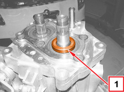
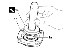
1. Fit a new oil seal (1a) on the differential flange (1b) using the tool (1c).
|
1875016000 |
Fitting tool |
Fitting differential right shaft oil seal Fitting engine side oil seal for manual gearbox to engine support Fitting differential flange oil seal |
1.4 8v 1.4 16v 1.4 16v TJet 120 HP 1.4 MultiAir 1.4 Turbo MultiAir (5 SPEEDS) 1.3 MultiJet 85/95 HP 0.9 TwinAir |
|
|
|
- Fit the differential flange and secure it by tightening the screws to the prescribed torque.
- Fit the left differential inner driveshaft.
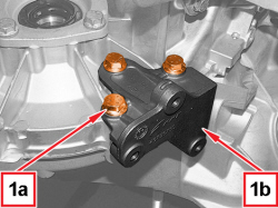
- Fit the gear selection/engagement mounting bracket and secure it using the screws.
- Loosen the retainers and remove the gearbox together with the differential from the support mount.
|
|
Two operators are needed for this operation.
|
|
1871001014 |
Gearbox support |
Gearbox overhaul |
|
- Remove the support tool from the overhaul stand and store it.
- Position the gearbox and differential on the tool used for the removing-refitting from the vehicle.
|
1860873000 |
Gearbox support |
Removing/refitting gearbox from the vehicle |
1.4 8v 1.4 16v TJet 120 HP 1.4 Turbo MultiAir (5 SPEEDS) 1.3 MultiJet 85/95 HP |
|
|
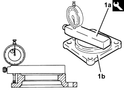
1. Position the tool (1a) complete with dial gauge on the differential sealing cover (1b), as shown in the figure, and measure the difference.
|
1895655000 |
Mount |
Determining thickness of differential bearing scraper ring |
1.4 8v 1.4 16v 1.4 16v TJet 120 HP 1.4 MultiAir 1.4 Turbo MultiAir (5 SPEEDS) 0.9 TwinAir 1.3 MultiJet 85/95 HP |
- Calculate the size of the thrust ring for differential bearing pre-loading by adding 0.12 mm to the difference measured.
|
|
0.12 corresponds to the prescribed interference for the bedding in and pre-loading of the differential bearings.
|
|
APPLIES TO VERSIONS WITH: From 04/2012
|
|
Removing
(
Refitting
)
| During removal/refitting of gears at the press, observe the following in order not to damage the teeth: - the gear/plate bearing surface must be as large as possible; - insert an aluminium sheet of suitable thickness between the gear and the plate. |
|
|
APPLIES TO VERSIONS WITH: From 04/2012
|
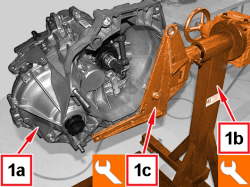
1. Fit the gearbox with differential (1a) on the overhaul stand (1b) using the support (1c).
|
1871000000 |
Rotating stand |
Gearbox overhaul |
1.4 8v 1.4 16v TJet 120 HP 1.4 Turbo MultiAir (5 SPEEDS) 1.3 MultiJet 85/95 HP |
|
1871001014 |
Mount |
Gearbox support for overhaul stand |
|
|
|
Two operators are needed for this operation.
|
|
|
APPLIES TO VERSIONS WITH: From 04/2012
|
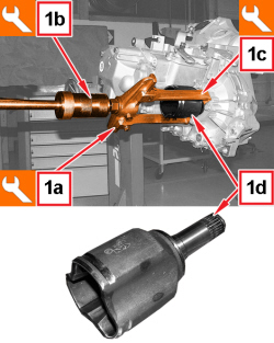
1. Use tools (1a), (1b) and (1c), to remove the differential left inner driveshaft (1d).
|
1840005001 |
Steering knuckle |
Differential inner driveshafts removal Removing bearings/hobs/main shaft-layshaft |
1.4 8v 1.4 16v TJet 120 HP 1.4 Turbo MultiAir (5 SPEEDS) 1.3 MultiJet 85/95 HP |
|
1847017001 |
Mallet |
Extracting bearings Differential inner driveshafts removal |
1.4 8v 1.4 16v TJet 120 HP 1.4 Turbo MultiAir 1.3 MultiJet 85/95 HP 1.6 JTD 16v |
|
1840005303 |
Hooks |
Differential inner driveshafts removal Removing layshaft rear bearing Removing 3rd speed driven gear and 2nd speed driven gear Removing 3rd and 4th speed engagement sliding sleeve hub, synchroniser ring and 3rd speed drive gear |
1.4 8v 1.4 16v TJet 120 HP 1.4 Turbo MultiAir (5 SPEEDS) 1.3 MultiJet 85/95 HP |
|
|
APPLIES TO VERSIONS WITH: From 04/2012
APPLIES TO VERSIONS WITH: From 04/2012
|
|
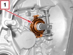
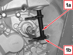
- Remove the outer clutch thrust control linkage retaining ring.
- Remove the outer clutch thrust control linkage.
|
|
APPLIES TO VERSIONS WITH: From 04/2012
APPLIES TO VERSIONS WITH: From 04/2012
APPLIES TO VERSIONS WITH: From 04/2012
APPLIES TO VERSIONS WITH: From 04/2012
APPLIES TO VERSIONS WITH: From 04/2012
APPLIES TO VERSIONS WITH: From 04/2012
|
|
- Engage any gear using the gear selection/engagement lever.
|
|
APPLIES TO VERSIONS WITH: From 04/2012
APPLIES TO VERSIONS WITH: From 04/2012
|
|
- Engage the 5th speed by pressing the fork on the main shaft.
|
|
If two gears are engaged simultaneously the gear shafts will lock.
|
|
|
APPLIES TO VERSIONS WITH: From 04/2012
APPLIES TO VERSIONS WITH: From 04/2012
APPLIES TO VERSIONS WITH: From 04/2012
|
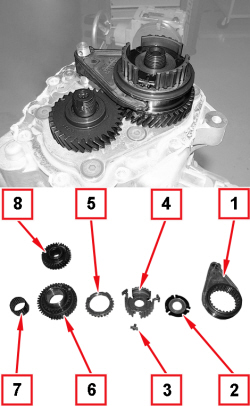
1. Remove the 5th speed drive fork along with the 5th speed sliding sleeve.
2. Remove the retaining flange for the pre-synchronizer mountings.
3. Remove the pre-synchronizer mountings.
4. Remove the 5th speed engagement sliding sleeve hub.
5. Remove the 5th speed pre-synchronizer ring.
6. Remove the 5th speed drive gear.
7. Remove the needle bearing for the 5th speed drive gear.
8. Remove the 5th speed driven gear.
|
|
APPLIES TO VERSIONS WITH: From 04/2012
|
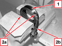
1. Position the 5th speed sliding sleeve in a vice with protective jaws.
2. Apply a brass punch on the two ends (2a) of the fork (2b) alternatively, until they are released from the 5th speed sliding sleeve.
|
|
Take care not to nick the tapered part of the sleeve and the ends of the fork with the drift.
|
|
|
APPLIES TO VERSIONS WITH: From 04/2012
APPLIES TO VERSIONS WITH: From 04/2012
APPLIES TO VERSIONS WITH: From 04/2012
APPLIES TO VERSIONS WITH: From 04/2012
|
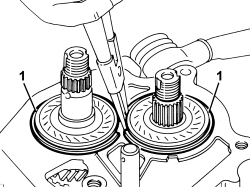
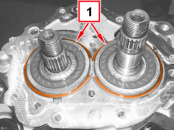
1. Remove the main and layshaft rear bearing retaining rings
|
|
To remove the retaining rings, arrange them with their openings at the front.
|
|
|
APPLIES TO VERSIONS WITH: From 04/2012
|
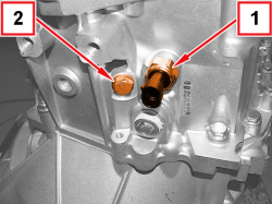
1. Undo the reversing light switch and remove it.
2. Undo the reverse idler gear shaft fixing screw.
|
|
APPLIES TO VERSIONS WITH: From 04/2012

|
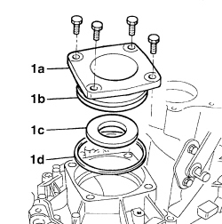
1. Undo the screws (1a) and remove the left flange on the differential (1b) with included oil seal and gasket (1c).
2. Remove the differential bearing preload thrust ring.
|
|
APPLIES TO VERSIONS WITH: From 04/2012
|
|
- Operate the gear selector/engagement lever and put the gearbox in neutral.
|
|
APPLIES TO VERSIONS WITH: From 04/2012
APPLIES TO VERSIONS WITH: From 04/2012
APPLIES TO VERSIONS WITH: From 04/2012
APPLIES TO VERSIONS WITH: From 04/2012
APPLIES TO VERSIONS WITH: From 04/2012
APPLIES TO VERSIONS WITH: From 04/2012
|
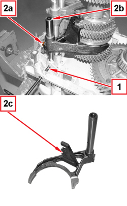
1. Remove the pin used for locking the gear engagement fork control rods.
2. Undo the screw (2a), extract the rod (2b) and remove it with the 1st-2nd speed drive fork (2c).
|
|
APPLIES TO VERSIONS WITH: From 04/2012
|
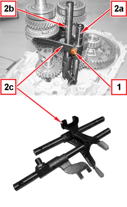
1. Undo the 3rd-4th speed fork fixing screw from the relevant rod.
2. Extract the 3rd-4th speed drive rod (2a) and the 5th-reverse speed drive rod (2b) simultaneously, then remove them along with the 3rd-4th speed fork (2c).
|
|
APPLIES TO VERSIONS WITH: From 04/2012
APPLIES TO VERSIONS WITH: From 04/2012
|
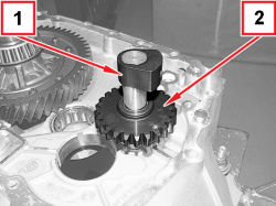
1. Remove the reverse idler gear shaft fixing screw support.
2. Remove the reverse idler gear.
|
|
APPLIES TO VERSIONS WITH: From 04/2012
|
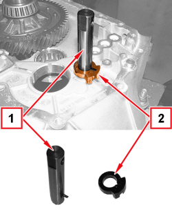
1. Remove the reverse idler gear shaft complete with centring pin.
2. Remove the locating bush.
|
|
APPLIES TO VERSIONS WITH: From 04/2012
APPLIES TO VERSIONS WITH: From 04/2012
APPLIES TO VERSIONS WITH: From 04/2012
APPLIES TO VERSIONS WITH: From 04/2012
|
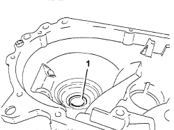
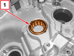
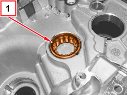
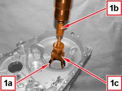
1. Remove the outer race (1a) for the right side differential bearing from the manual gearbox bellhousing, using tools (1b) and (1c).
|
1847017001 |
Mallet |
Extracting bearings Differential inner driveshafts removal |
1.4 8v 1.4 16v TJet 120 HP 1.4 Turbo MultiAir 1.3 MultiJet 85/95 HP 1.6 JTD 16v |
|
1870655000 |
Extractor/fitting tool |
Bearing race removal |
1.4 16v TJet 1.6 JTD 16v 1.3 MultiJet 1.4 Turbo MultiAir |
|
|
APPLIES TO VERSIONS WITH: From 04/2012
APPLIES TO VERSIONS WITH: From 04/2012
|
|
- Position the gearbox casing in a vice equipped with protective jaws.
|
|
APPLIES TO VERSIONS WITH: From 04/2012
APPLIES TO VERSIONS WITH: From 04/2012
|
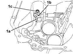
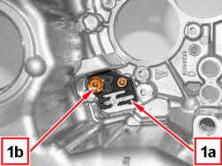
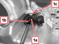
1. Turn the gear selector/engagement lever to access the dog fixing pin.
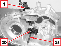
2. Keep the gear selector/engagement lever pressed and use a suitable punch (2a) to remove the dog fixing pin (2b).
|
|
APPLIES TO VERSIONS WITH: From 04/2012
|
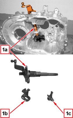
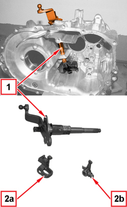
1. Take out and remove the gear selector/engagement lever.
2. Remove the gear selector/engagement rod inner mounting bracket (2a) and the dog (2b).
|
|
APPLIES TO VERSIONS WITH: From 04/2012
APPLIES TO VERSIONS WITH: From 04/2012
APPLIES TO VERSIONS WITH: From 04/2012
|
|
DISASSEMBLE THE LAYSHAFT OPERATING AS DESCRIBED BELOW
|
|
APPLIES TO VERSIONS WITH: From 04/2012
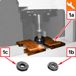
|
1. On the hydraulic press using the tool (1a), remove the rear bearing (1b) and the 4th speed driven gear (1c).
|
2000005000 |
Plate |
Reaction plate in the press |
1.4 8v 1.4 16v TJet 1.6 JTD 16v M32 1.3 MultiJet 1.4 Turbo MultiAir |
|
|
APPLIES TO VERSIONS WITH: From 04/2012
APPLIES TO VERSIONS WITH: From 04/2012
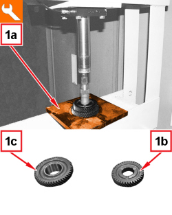
|
1. On the hydraulic press using the tool (1a), remove the 3th speed driven gear (1b) and the 2nd speed driven gear (1c).
|
2000005000 |
Plate |
Reaction plate in the press |
1.4 8v 1.4 16v TJet 1.6 JTD 16v M32 1.3 MultiJet 1.4 Turbo MultiAir |
|
|
APPLIES TO VERSIONS WITH: From 04/2012
|
|
- Position the layshaft in a vice fitted with protective jaws.
|
|
APPLIES TO VERSIONS WITH: From 04/2012
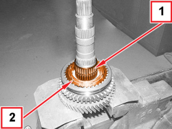
|
1. Remove the needle bearing for the 2nd speed driven gear.
2. Remove the 2nd speed synchronizer ring assembly.
|
|
APPLIES TO VERSIONS WITH: From 04/2012
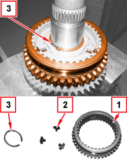
|
1. Remove the 1st-2nd and reverse engagement sliding sleeve.
2. Remove the pre-synchronizer mountings.
3. Remove the 1st-2nd and reverse sliding sleeve hub retaining ring.
|
|
When refitting, replace the retaining circlip.
|
|
|
APPLIES TO VERSIONS WITH: From 04/2012
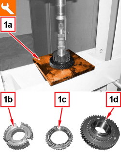
|
1. On the hydraulic press, use the tool (1a) to remove the 1st-2nd and reverse sliding engagement sleeve hub (1b), the 1st speed synchronizer ring assembly (1c) and the 1st speed driven gear (1d).
|
2000005000 |
Plate |
Reaction plate in the press |
1.4 8v 1.4 16v TJet 1.6 JTD 16v M32 1.3 MultiJet 1.4 Turbo MultiAir |
|
|
APPLIES TO VERSIONS WITH: From 04/2012
APPLIES TO VERSIONS WITH: From 04/2012
|
|
|
|
The layshaft front bearing inner race cannot be removed; if necessary, replace it together with the layshaft.
|
|
|
APPLIES TO VERSIONS WITH: From 04/2012
|
|
DISASSEMBLE THE MAIN SHAFT OPERATING AS DESCRIBED BELOW
|
|
APPLIES TO VERSIONS WITH: From 04/2012
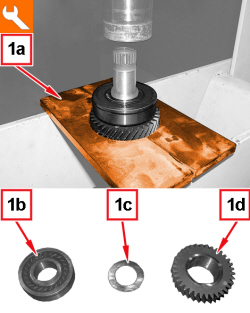
|
1. On the hydraulic press using the tool (1a), remove the rear bearing (1b), the spacer (1c) and the 4th speed drive gear (1d).
|
1870899400 |
Half plates |
Removing main/layshaft bearings/gears/hubs/synchroniser rings |
1.4 8v 1.4 16v 1.4 16v TJet 120 HP 1.4 MultiAir 1.4 Turbo MultiAir (5 SPEEDS) 1.3 MultiJet 85/95 HP 0.9 TwinAir |
|
|
APPLIES TO VERSIONS WITH: From 04/2012
|
|
- Position the main shaft in a vice fitted with protective jaws.
|
|
APPLIES TO VERSIONS WITH: From 04/2012
APPLIES TO VERSIONS WITH: From 04/2012
APPLIES TO VERSIONS WITH: From 04/2012
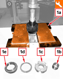
|
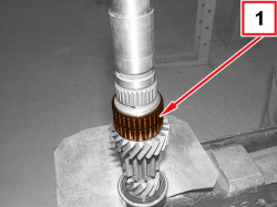
1. On the hydraulic press, use the tool (1a) to remove the 4th speed drive gear bushing (1b), the 3rd-4th speed sliding sleeve hub (1c) the 3rd speed synchronizer ring (1d) and the 3rd speed drive gear (1e).
|
2000005000 |
Plate |
Reaction plate in the press |
1.4 8v 1.4 16v TJet 1.6 JTD 16v M32 1.3 MultiJet 1.4 Turbo MultiAir |
|
|
APPLIES TO VERSIONS WITH: From 04/2012
APPLIES TO VERSIONS WITH: From 04/2012
APPLIES TO VERSIONS WITH: From 04/2012
APPLIES TO VERSIONS WITH: From 04/2012
|
|
REASSEMBLE THE MAIN SHAFT OPERATING AS DESCRIBED BELOW
|
|
APPLIES TO VERSIONS WITH: From 04/2012
APPLIES TO VERSIONS WITH: From 04/2012
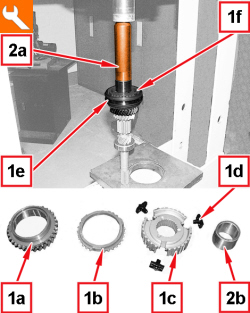
|
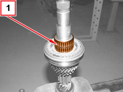
1. Fit the 3rd speed drive gear (1a), the 3rd speed synchronizer ring (1b), the 3rd-4th speed sliding sleeve hub (1c), the pre-synchronizer mountings (1d), the 3rd-4th sliding sleeve (1e) and the 4th speed synchroniser ring (1f).
2. On the hydraulic press using the tool (2a), fit the bushing for the 4th speed drive gear (2b).
|
1870659000 |
Fitting tool |
Fitting main shaft bearings Fitting main shaft bushing |
1.4 16v TJet 120 HP 1.4 Turbo MultiAir (5 SPEEDS) 1.3 MultiJet 85/95 HP |
|
|
APPLIES TO VERSIONS WITH: From 04/2012
APPLIES TO VERSIONS WITH: From 04/2012
|
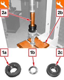
1. Fit the 4th speed drive gear (1a) and the shim (1b).
2. On the hydraulic press, using tools (2a) and (2b) fit the rear bearing (2c).
|
1870659000 |
Fitting tool |
Fitting main shaft bearings Fitting main shaft bushing |
1.4 16v TJet 120 HP 1.4 Turbo MultiAir (5 SPEEDS) 1.3 MultiJet 85/95 HP |
|
2000005000 |
Plate |
Reaction plate in the press |
1.4 8v 1.4 16v TJet 1.6 JTD 16v M32 1.3 MultiJet 1.4 Turbo MultiAir |
|
|
APPLIES TO VERSIONS WITH: From 04/2012
|
|
REASSEMBLE THE LAYSHAFT OPERATING AS DESCRIBED BELOW
|
|
APPLIES TO VERSIONS WITH: From 04/2012
APPLIES TO VERSIONS WITH: From 04/2012
|
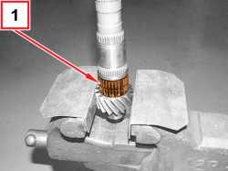
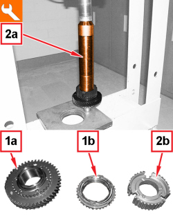
1. Fit the 1st speed driven gear (1a) and 1st speed synchronizer ring assembly (1b).
2. On the hydraulic press, using tool (2a) fit the 1st-2nd and reverse sliding sleeve hub (2b).
|
1870658000 |
Extractor/fitting tool |
Fitting main/layshaft bearings/hubs/gears |
1.4 8v 1.4 16v TJet 1.6 JTD 16v 1.3 MultiJet 1.4 Turbo MultiAir |
|
|
APPLIES TO VERSIONS WITH: From 04/2012
|
|
- Position the layshaft in a vice fitted with protective jaws.
|
|
APPLIES TO VERSIONS WITH: From 04/2012
|
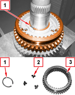
1. Fit a new 1st-2nd and reverse sliding sleeve hub retaining ring.
2. Fit the pre-synchronizer mountings in their housings in the 1st-2nd and reverse sliding sleeve hub.
3. Fit the 1st-2nd and reverse engagement sliding sleeve.
|
|
APPLIES TO VERSIONS WITH: From 04/2012
|
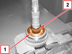
1. Fit the 2nd speed synchronizer rings assembly.
2. Fit the needle bearing for the 2nd speed driven gear.
|
|
APPLIES TO VERSIONS WITH: From 04/2012
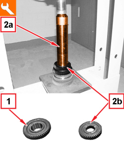
|
1. Fit the 2nd speed driven gear.
2. On the hydraulic press using the tool (2a), fit the 3rd speed driven gear (2b).
|
1870658000 |
Extractor/fitting tool |
Fitting main/layshaft bearings/hubs/gears |
1.4 8v 1.4 16v TJet 1.6 JTD 16v 1.3 MultiJet 1.4 Turbo MultiAir |
|
|
APPLIES TO VERSIONS WITH: From 04/2012
APPLIES TO VERSIONS WITH: From 04/2012
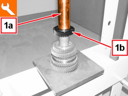
|
1. On the hydraulic press using the tool (1a), fit the 4th speed driven gear (1b).
|
1870465000 |
Fitting tool |
Fitting 3rd speed driven gear/4th speed driven gear Fitting layshaft rear bearing |
1.4 16v TJet 120 HP 1.4 Turbo MultiAir (5 SPEEDS) 1.3 MultiJet 85/95 HP |
|
|
APPLIES TO VERSIONS WITH: From 04/2012
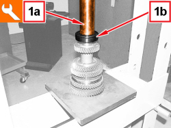
|
1. On the hydraulic press using the tool (1a), fit the rear bearing (1b).
|
1870465000 |
Fitting tool |
Fitting 3rd speed driven gear/4th speed driven gear Fitting layshaft rear bearing |
1.4 16v TJet 120 HP 1.4 Turbo MultiAir (5 SPEEDS) 1.3 MultiJet 85/95 HP |
|
|
APPLIES TO VERSIONS WITH: From 04/2012
|
|
- Position the gearbox casing in a vice equipped with protective jaws.
|
|
APPLIES TO VERSIONS WITH: From 04/2012
APPLIES TO VERSIONS WITH: From 04/2012
APPLIES TO VERSIONS WITH: From 04/2012
APPLIES TO VERSIONS WITH: From 04/2012
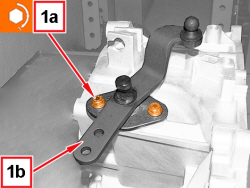
|
1. Tighten the gear selector/engagement lever (1b) fixing screws (1a) to the prescribed torque.
|
Gear selection/engagement lever |
Screw |
M8 |
2.1 ÷ 2.6 |
1.4 16v TJet 120 HP 1.4 Turbo MultiAir (5 SPEEDS) 1.3 MultiJet 85/95 HP |
|
|
APPLIES TO VERSIONS WITH: From 04/2012
|
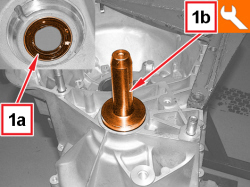
1. Fit a new engine side oil seal ring (1a) on the manual gearbox bellhousing using the tool (1b).
|
1875016000 |
Fitting tool |
Fitting differential right shaft oil seal Fitting engine side oil seal for manual gearbox to engine support Fitting differential flange oil seal |
1.4 8v 1.4 16v 1.4 16v TJet 120 HP 1.4 MultiAir 1.4 Turbo MultiAir (5 SPEEDS) 1.3 MultiJet 85/95 HP 0.9 TwinAir |
|
|
APPLIES TO VERSIONS WITH: From 04/2012
|
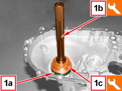
1. Fit the outer race (1a) for the right side differential bearing on the gearbox bellhousing, using tools (1b) and (1c).
|
1870898400 |
Grip |
Fitting of bearing outer race |
1.4 16v TJet 120 HP 1.4 Turbo MultiAir 1.3 MultiJet 85/95 HP 1.6 JTD 16v |
|
1874541000 |
Fitting tool |
Fitting differential support bearing outer races |
1.4 16v TJet 120 HP 1.4 Turbo MultiAir (5 SPEEDS) 1.3 MultiJet 85/95 HP |
|
|
APPLIES TO VERSIONS WITH: From 04/2012
APPLIES TO VERSIONS WITH: From 04/2012
APPLIES TO VERSIONS WITH: From 04/2012
APPLIES TO VERSIONS WITH: From 04/2012
|
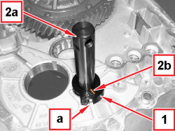
1. Fit the bushing for the reverse idler gear shaft.
|
|
Position the groove (a) of the bushing next to the rib, as shown in the figure.
|
2. Fit the reverse idler gear shaft (2a) by placing the pin (2b) in its housing on the bushing.
|
|
APPLIES TO VERSIONS WITH: From 04/2012
|
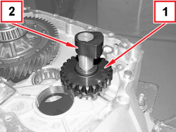
1. Fit the reverse idler gear.
|
|
Make sure that the gear engagement teeth are facing downwards.
|
2. Fit the reverse idler gear shaft fixing screw support.
|
|
APPLIES TO VERSIONS WITH: From 04/2012
APPLIES TO VERSIONS WITH: From 04/2012
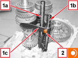
|
1. Fit the 5th-reverse rod (1a) and the 3rd-4th speed control rod (1b) complete with fork (1c) simultaneously.
2. Tighten the screw for the 3rd-4th speed fork to the prescribed torque.
|
3rd and 4th speed control fork |
Screw |
M6 |
1.5 ÷ 1.9 |
1.4 16v TJet 120 HP 1.4 Turbo MultiAir (5 SPEEDS) 1.3 MultiJet 85/95 HP |
|
|
APPLIES TO VERSIONS WITH: From 04/2012
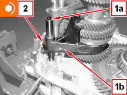
|
1. Fit the 1st-2nd speed control rod (1a) complete with fork (1b).
2. Tighten the screw for the 1st-2nd speed fork to the prescribed torque.
|
1st and 2nd speed control fork |
Screw |
M6 |
1.5 ÷ 1.9 |
1.4 16v TJet 120 HP 1.4 Turbo MultiAir (5 SPEEDS) 1.3 MultiJet 85/95 HP |
|
|
APPLIES TO VERSIONS WITH: From 04/2012

|
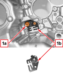
1. Fit the mounting with reverse engagement fork lever (1a) and tighten the screws (1b) to the prescribed torque.
|
Reverse control fork mounting bracket |
Screw |
M6 |
8.5 ÷ 11.1 |
1.4 16v TJet 120 HP 1.4 Turbo MultiAir (5 SPEEDS) 1.3 MultiJet 85/95 HP |
|
|
APPLIES TO VERSIONS WITH: From 04/2012
APPLIES TO VERSIONS WITH: From 04/2012
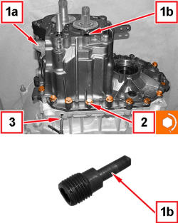
|
- Apply sealant to the contact surfaces between the manual gearbox bellhousing and the gearbox casing.
1. Fit the gearbox casing (1a) on the manual gearbox bellhousing and tighten the gear selector/engagement lever inner support locking pin (1b).
2. Tighten the screws fixing the gearbox casing to the manual gearbox bellhousing to the prescribed torque.
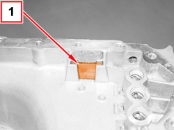
|
Gearbox casing |
Screw |
M8 |
2.1 ÷ 2.6 |
1.4 16v TJet 120 HP 1.4 Turbo MultiAir (5 SPEEDS) 1.3 MultiJet 85/95 HP |
3. Remove the gear engagement fork control rod locking pin and tighten the relevant cap.
|
|
APPLIES TO VERSIONS WITH: From 04/2012
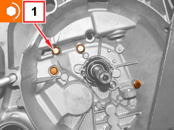
|
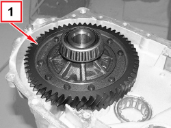
1. Tighten the inner screws fixing the manual gearbox bellhousing to the manual gearbox casing to the prescribed torque.
|
Gearbox casing |
Screw |
M8 |
2.1 ÷ 2.6 |
1.4 16v TJet 120 HP 1.4 Turbo MultiAir (5 SPEEDS) 1.3 MultiJet 85/95 HP |
|
|
APPLIES TO VERSIONS WITH: From 04/2012
|
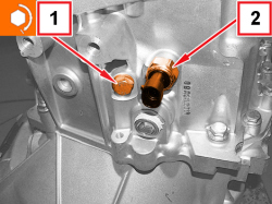
1. Tighten the reverse idler gear shaft screw to the prescribed torque.
|
Reverse shaft |
Screw |
M8 |
2.9 ÷ 3.6 |
1.4 16v TJet 120 HP 1.4 Turbo MultiAir (5 SPEEDS) 1.3 MultiJet 85/95 HP |
2. Fit the reversing light switch.
|
|
APPLIES TO VERSIONS WITH: From 04/2012
|
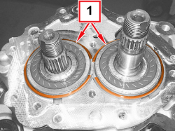
1. Fit the main and layshaft rear bearing circlips.
|
|
Position the retaining rings with their openings at the front to facilitate fitting.
|
|
|
APPLIES TO VERSIONS WITH: From 04/2012
|
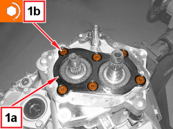
1. Fit main and layshaft rear bearing retaining plate (1a) and secure it by tightening screws (1b) to the prescribed torque.
|
Main and layshaft rear bearing retaining plate |
Screw |
M8 |
2.1 ÷ 2.6 |
1.4 16v TJet 120 HP 1.4 Turbo MultiAir (5 SPEEDS) 1.3 MultiJet 85/95 HP |
|
|
APPLIES TO VERSIONS WITH: From 04/2012
|
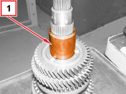
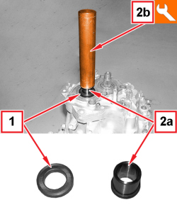
1. Fit the spacer.
2. Fit the bush for 5th speed drive gear (2a) using the tool (2b).
|
1871004500 |
Fitting tool |
Fitting 5th speed drive gear bush |
1.4 16v TJet 120 HP 1.4 Turbo MultiAir (5 SPEEDS) 1.3 MultiJet 85/95 HP |
|
|
APPLIES TO VERSIONS WITH: From 04/2012
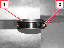
|
1. Position the 5th speed sliding sleeve in a vice with protective jaws.
2. Position the fork so that the tapered part is in the same direction as that of the sleeve, resting it against the shoulder on the side where the sleeve diameter is smaller;
- fit the fork manually, exerting the necessary pressure, until it is completely inserted in the sleeve.
|
|
When the fitting is complete, check that the sleeve can rotate freely inside the fork.
|
|
|
APPLIES TO VERSIONS WITH: From 04/2012
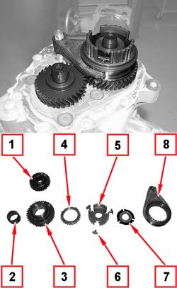
|
1. Fit the 5th speed driven gear.
2. Fit the needle bearing for the 5th speed drive gear.
3. Fit the 5th speed drive gear.
4. Fit the 5th speed synchronizer ring.
5. Fit the 5th speed engagement sliding sleeve hub.
6. Fit the pre-synchronizer mountings.
7. Fit the retaining flange for the pre-synchronizer mountings.
8. Fit the 5th speed sliding sleeve complete with drive fork.
|
|
APPLIES TO VERSIONS WITH: From 04/2012
|
|
- Engage any gear using the gear selection/engagement lever.
- Engage 5th speed by pressing the main shaft drive fork.
|
|
If two gears are engaged simultaneously the gear shafts will lock.
|
|
|
APPLIES TO VERSIONS WITH: From 04/2012
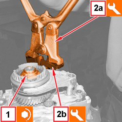
|
1. Tighten the new ring nuts for the main and layshafts to the prescribed torque.
|
Main and layshaft ring nuts |
Ring nut |
M20 |
10 ÷ 12.4 |
1.4 16v TJet 120 HP 1.4 Turbo MultiAir (5 SPEEDS) 1.3 MultiJet 85/95 HP |
2. Stake the main and layshaft ring nuts using the tools (2a) and (2b).
|
1874140001 |
Pliers |
Staking ring nuts securing main and layshaft 5th speed |
1.4 8v 1.4 16v 1.4 16v TJet 120 HP 1.4 MultiAir 1.4 Turbo MultiAir (5 SPEEDS) 1.3 MultiJet 85/95 HP 0.9 TwinAir |
|
1874140005 |
Pair of heads |
Staking ring nuts securing main and layshaft 5th speed |
1.4 8v 1.4 16v 1.4 16v TJet 120 HP 1.4 MultiAir 1.4 Turbo MultiAir (5 SPEEDS) 1.3 MultiJet 85/95 HP 0.9 TwinAir |
|
|
APPLIES TO VERSIONS WITH: From 04/2012
|
|
- Place the 5th speed control fork in neutral.
|
|
APPLIES TO VERSIONS WITH: From 04/2012
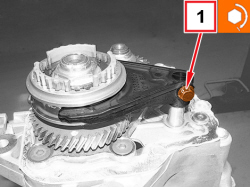
|
1. Tighten the screw for the 5th speed control fork to the prescribed torque.
|
5th speed control fork |
Screw |
M6 |
1.5 ÷ 1.9 |
1.4 16v TJet 120 HP 1.4 Turbo MultiAir (5 SPEEDS) 1.3 MultiJet 85/95 HP |
|
|
APPLIES TO VERSIONS WITH: From 04/2012
|
|
- Apply the prescribed sealant to the contact surfaces between the gearbox casing and the manual gearbox rear cover.
|
|
APPLIES TO VERSIONS WITH: From 04/2012
|
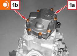
1. Fit the rear cover (1a) and secure it by tightening the screws (1b) to the prescribed torque.
|
Rear cover |
Screw |
M8 |
2.1 ÷ 2.6 |
1.4 16v TJet 120 HP 1.4 Turbo MultiAir (5 SPEEDS) 1.3 MultiJet 85/95 HP |
|
|
APPLIES TO VERSIONS WITH: From 04/2012
|
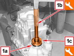
1. Fit the left differential bearing outer race (1a) using tools (1b) and (1c).
|
1870898400 |
Grip |
Fitting of bearing outer race |
1.4 16v TJet 120 HP 1.4 Turbo MultiAir 1.3 MultiJet 85/95 HP 1.6 JTD 16v |
|
1875055000 |
Fitting tool |
Fitting of bearing outer race |
1.4 16v TJet 120 HP 1.4 Turbo MultiAir (5 SPEEDS) 1.3 MultiJet 85/95 HP |
|
|
APPLIES TO VERSIONS WITH: From 04/2012
APPLIES TO VERSIONS WITH: From 04/2012
|
|
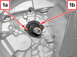
- Apply sealant to the contact surfaces between the gearbox inlet shaft gasket and the manual gearbox bellhousing.
|
|
APPLIES TO VERSIONS WITH: From 04/2012
APPLIES TO VERSIONS WITH: From 04/2012
APPLIES TO VERSIONS WITH: From 04/2012
APPLIES TO VERSIONS WITH: From 04/2012
|
|
- Fit the outer lever of the clutch thrust bearing control and the retaining circlip.
|
|
APPLIES TO VERSIONS WITH: From 04/2012
APPLIES TO VERSIONS WITH: From 04/2012
|
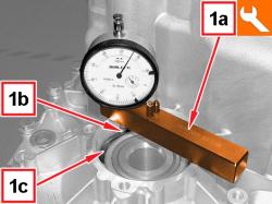
1. Fit the tool (1a) complete with dial gauge on the differential seal cover support surface, then bring the feeler gauge (1b) into contact with the taper roller bearing outer race (1c).
|
1895655000 |
Mount |
Determining thickness of differential bearing scraper ring |
1.4 8v 1.4 16v 1.4 16v TJet 120 HP 1.4 MultiAir 1.4 Turbo MultiAir (5 SPEEDS) 0.9 TwinAir 1.3 MultiJet 85/95 HP |
|
|
APPLIES TO VERSIONS WITH: From 04/2012
|
|
- Zero the dial gauge with a preload of 1 mm.
|
|
APPLIES TO VERSIONS WITH: From 04/2012
|
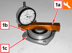
1. Position the tool (1a) complete with dial gauge on the differential sealing cover then bring the feeler gauge (1b) in contact with the surface (1c) and measure the difference.
|
1895655000 |
Mount |
Determining thickness of differential bearing scraper ring |
1.4 8v 1.4 16v 1.4 16v TJet 120 HP 1.4 MultiAir 1.4 Turbo MultiAir (5 SPEEDS) 0.9 TwinAir 1.3 MultiJet 85/95 HP |
|
|
APPLIES TO VERSIONS WITH: From 04/2012
|
|
- Calculate the size of the thrust ring for differential bearing pre-loading by adding 0.08 mm to the difference measured.
|
|
0.08 mm corresponds to the prescribed interference for the bedding-in and pre-loading of the differential bearings.
|
|
|
APPLIES TO VERSIONS WITH: From 04/2012
|
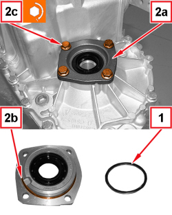
1. Place the thrust ring having the same size or the next largest size to the one calculated for the differential bearing pre-loading in the housing.
2. Fit the new sealing cover with included oil seal (2a) and the gasket (2b), then tighten the screws (2c) to the prescribed torque.
|
Left flange on differential |
Screw |
M8 |
2.0 + 45° |
|
|
|
The cover with included oil seal and the gasket must always be replaced.
|
|
|
APPLIES TO VERSIONS WITH: From 04/2012
|
|
- Fit the differential inner driveshaft.
- Undo the fastenings and remove the gearbox together with the differential from the support tools.
|
|
Two operators are needed for this operation.
|
|
|