CONSTRUCTION SPECIFICATIONS
The clutch is single dry plate, with flexible spring couplings and thrust release. The clutch release is implemented by a coaxial, hydraulically operated device known as the "CSC system".
Friction materials free from non ecological components have been used; special care has been taken over the development of new materials and the clutch assembly with a view to guaranteeing improved performance in terms of modularity and driving comfort with a consequent reduction in weight compared with a traditional hydraulic system. In particular, the clutch pump has undergone a considerable improvement compared with the components usually adopted.
CLUTCH HYDRAULIC SYSTEM
The coaxial, hydraulically operated clutch release system is known as the "CSC system". This type of control, which includes the hydraulic actuator with the thrust bearing, makes it possible to maintain the system performance throughout the life of the clutch and contributes to the reduction in noise and vibrations transmitted by the pedal.
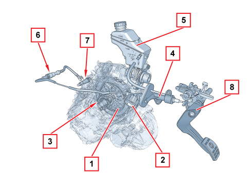
1. Clutch mechanism
2. Vibration damper
3. CSC actuator
4. Clutch pump
5. Brake-clutch fluid reservoir
6. Supplementary damper
7. Connector with bleed valve
8. Clutch pedal
Csc system
The CSC system is defined as coaxial because the release actuator comprises an aluminium ring cylinder fitted inside the bellhousing positioned between the gearbox and the clutch mechanisms, in a coaxial position in relation to the main shaft.
The advantage of the CSC system compared with traditional systems lies in the lack of kinematic couplings and sliding resulting in greater reliability, functionality and ease of maintenance.
The system features the following characteristics:
- constant height adjustment of the clutch pedal;
- constant force applied to the pedal over a period of time;
- elimination of any difficulties with the clutch pedal return;
- reduction in noise and vibrations transmitted by the pedal through the use of a vibration damper positioned in the cylinder oil pipe.
The pipe is connected to the actuator by means of a rapid connector with a built-in bleed.
The lack of the idler crank mechanism of the traditional system, the adoption of a clutch pump with a plastic casing and piston and the use of plastics for the construction of the pedal assembly as well, has also allowed a considerable reduction in the noise and overall weight of the system.
CSC HYDRAULIC ACTUATOR CYLINDER
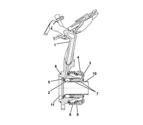
1. Oil intake pipe
2. Expansion chamber
3. Piston
4. Thrust bearing
5. Threaded closing flange
6. O-ring
7. Anti-wear pads
8. Rubber gaiter
9. Spring
10. Guide pipe
11. Oil seal housing
The clutch release takes place through the action of the clutch pump which sends oil under pressure, via the pipe (1), to the expansion chamber (2).
The pressure of the oil causes the movement of the piston (3) which slides in the guide pipe (10) by means of plastic anti-wear pads (7).
The piston is integral with the thrust bearing (4), which presses on the pressure plates, thereby releasing the clutch.
When the pressure of the oil is no longer present, the actuator returns to the rest position by means of the pressure plate spring's thrust.
An oil seal and an O-ring (6) guarantee the seal preventing any gearbox oil leaks that could occur inside the clutch bell housing.
There is a rubber boot (8), kept in position by a spring (9), as protection against the entry of any foreign bodies.
Clutch release pump
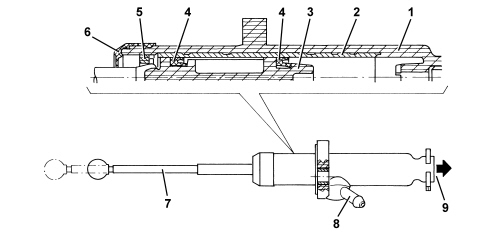
1. Casing
2. Steel cylinder
3. Piston
4. Gasket
5. Piston detent fork
6. Protective gaiter
7. Operating stem
8. Oil inlet
9. Oil intake to CSC actuator
The clutch release pump has been designed with a plastic piston and casing in order to reduce the weight, and with the operating stem secured (T interface) to the piston. There is a steel cylinder, inside the casing in the area where the piston seals slide, to prevent the wear and distortions which result from the pressure.
The piston is prevented from escaping by a V-shaped fork, whilst a protective boot prevents dirt from accumulating inside the cylinder.
The piston upper and lower end of travel positions in the pump casing also determine the upper and lower end positions of the pedal.